High-humidity golf and country club locker rooms fail when shower vapor, wet-turf shoe moisture, and tournament crowd surges overwhelm passive room ventilation and residential-grade cabinetry. Within 12 to 24 months of opening, under-exhausted changing rooms develop 75% to 85% relative humidity spikes that warp wood locker doors, corrode concealed hinges, wick mop water into uncurbed cabinet bases, track 6 to 12 liters of barefoot shower water onto dry dressing carpets, and trip 20A vanity circuit breakers whenever two post-round players switch on 1,875W hair dryers simultaneously.
Effective locker room design eliminates hygrothermal decay, aisle congestion, and wet-zone electrical hazards by combining a four-zone country club changing room layout with 8 to 10 ACH negative-pressure mechanical exhaust (-2.5 to -12.5 Pa), 100 to 150 mm (4 to 6 in.) moisture-proof locker curb plinths (ASTM D1037 <= 5% swell), >= 1.80 m (6.0 ft) to 2.45 m (8.0 ft) clear aisles around ADA §803 / §903 locker room benches, 1% to 2% (1/8 to 1/4 in./ft) wet-core drainage falls, and dedicated 20A Class A GFCI grooming circuits under NFPA 70 (NEC) Article 210.8(B).
While our foundational walk-through checklist in changing rooms: benches, hooks and water on the tile establishes the four baseline inspection questions to put to a specifier on site, locker room flooring: barefoot slip resistance, golf spike resistant carpet tiles, and epoxy grout details the floor-covering materials, friction testing standards, and dual-pH scrubbing chemistry, golf clubhouse design and member-visitor flow maps how the locker core connects to the exterior bag drop, pro shop, and 19th-hole spike bar across the wider building, and golf cart storage building design: stall dimensions, NEC 625 fleet charging, and hydrogen exhaust covers high-point roof-ridge hydrogen dilution (1.0 cfm/sq ft) and NEC Article 625 fleet charging in the back-of-house cart barn, this specification reference provides the internal engineering calculations and construction tolerances required within the sports facilities discipline.
| Locker Room Zone | Static Pressure Target | Ventilation & Exhaust Rate (ASHRAE 62.1 / Surge) | Flooring & Drainage Specification | Millwork, Bench & Electrical Standard |
|---|---|---|---|---|
| Zone 1: Sightline-Baffled Entry & Shoe-Care Vestibule | 0 Pa Reference (Outer corridor at +2.5 to +5.0 Pa) |
10%–15% inward conditioned transfer air (Q_transfer) across acoustic labyrinth |
8–10 mm vulcanized rubber over moisture-mitigated slab; dry scrape/wipe transition |
90°/180° WBDG sightline baffle (STC 50+, NRC >= 0.70); spike-change bench & valet buffer |
| Zone 2: Dry Carpeted Locker Bays & Member Lounge | -2.5 to -5.0 Pa (-0.01 to -0.02 in. w.g.) |
Code min 0.50 cfm/sq ft continuous; 8–10 ACH peak surge; 8–15 cfm/locker crown plenum |
Solution-dyed nylon 6,6 cut-pile carpet tile with impervious cushion backing (0% slope) |
ANSI/AWI 0641 wood lockers on 100–150 mm plinth (ASTM D1037 <= 5%); >= 1.80–2.45 m aisles; ADA §903 benches |
| Zone 3: Toweling Buffer & Grooming Vanity Alcove | -5.0 to -7.5 Pa (-0.02 to -0.03 in. w.g.) |
Swept transfer air from Zone 2 toward wet core + local vanity canopy slot extraction | R11 unglazed porcelain tile pitched 1.0%–1.5% (1:80) to secondary trench drain + capillary break |
4–5 ft drying depth; slatted ADA §903.7 bench; NEC §210.8(B)(11) Class A GFCI @ 36–42 in. AFF (>= 6 ft from shower) |
| Zone 4: Wet Shower, Steam & Sanitary Core | -7.5 to -12.5 Pa (-0.03 to -0.05 in. w.g.) |
10–15 ACH wet surge; 20/50 cfm per shower head + 50/70 cfm per WC/urinal (100% roof exhaust) |
R11/R12 barefoot tile (DIN 51097 B/C) pitched 1.5%–2.0% (1/8–1/4 in./ft, max 1:48) to 316 SS linear drain |
EN 438 / NEMA LD 3 solid phenolic partitions; ADA §608 36×36 in. transfer or 30×60 in. roll-in stalls; zero receptacles (NEC §406.9(C)) |
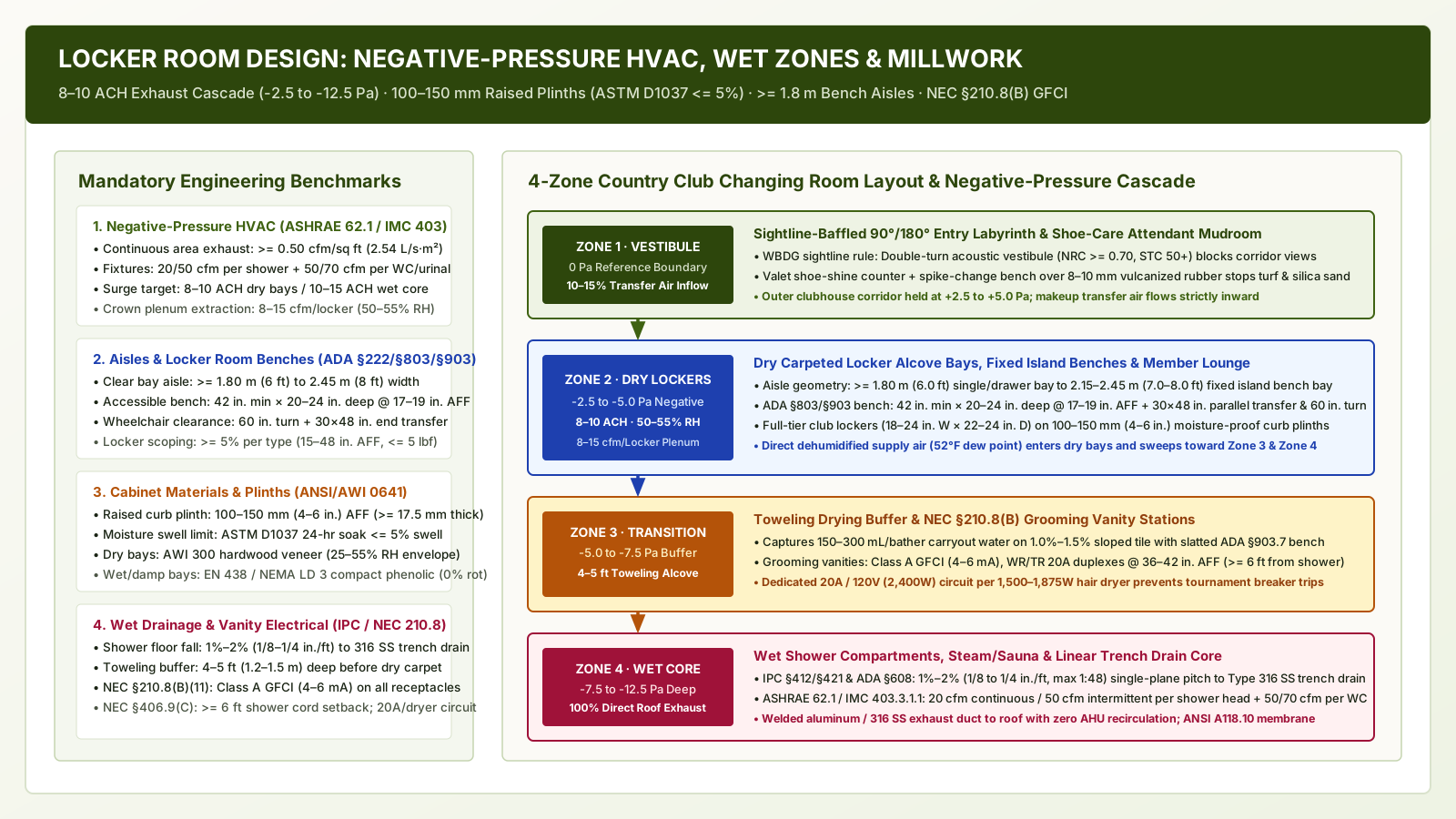
1. Negative-Pressure HVAC & Cabinet Exhaust Engineering: 8–10 ACH, ASHRAE 62.1 Rates, and Latent Dehumidification
Key takeaway: Size mechanical exhaust for a code baseline of 0.50 cfm/sq ft plus 20/50 cfm per shower head under ASHRAE 62.1, scale peak tournament extraction to 8 to 10 ACH in dry locker bays (10 to 15 ACH in wet shower cores), supply 85% to 90% dehumidified makeup air (<= 52°F dew point for 50%–55% RH) to hold -2.5 to -12.5 Pa cascading negative pressure, and extract 8 to 15 cfm per locker through top crown plenums.
Why Country Club Locker Rooms Fail Hygrothermally During Post-Round Waves
Unlike commercial office changing rooms with steady, low-moisture occupancy, a golf clubhouse locker room experiences extreme bimodal moisture spikes driven by tee-sheet waves and shotgun tournament finishes. As analyzed in moving guests through a club on event day, a full-field 18-hole shotgun tournament returns 144 players off the course within a 15-to-25-minute window. Inside the men’s or women’s locker sanctuary, 12 to 24 shower heads discharge simultaneously at 105°F to 110°F (40.5°C to 43.3°C), releasing 350 to 550 grains of water vapor per minute per active shower, while 60 to 120 players stow sweat-soaked shirts, damp rain suits, and wet leather golf shoes inside closed cabinet doors.
If the mechanical system supplies standard comfort-cooling air (55°F to 58°F supply temperature tied only to a wall dry-bulb thermostat) or operates at neutral/positive static pressure relative to the clubhouse hallway, three compounding failures occur:
- Latent Humidity Runaway (
> 70%–85% RH): Once sensible room temperature satisfies the wall thermostat (72°F/22.2°C), the cooling coil cycles off while latent moisture from showers, wet towels, and damp shoes continues evaporating. Relative humidity climbs past75% RH, condensing on uninsulated domestic cold-water lines, ceiling diffusers, and mirror glass. - Cabinet Interior Stagnation & Mold (
ASTM G21Failure): Closed wooden lockers trap a microclimate above68% to 75% RH, allowing Aspergillus and Penicillium mildew spores to colonize leather golf shoes, wool sweaters, and unsealed wood veneer backs within72 hours. - Corridor Odor Migration: Every door swing or positive-pressure imbalance pushes warm, humid air laden with volatile organic sulfur and ammonia compounds from damp turf and athletic gear outward into the formal reception lobby and 19th-hole grill.
ANSI/ASHRAE Standard 62.1, IMC Table 403.3.1.1, and 8–10 ACH Surge Sizing
To prevent moisture accumulation and odor bleed, mechanical ventilation specifications must reconcile code-minimum baseline exhaust under ANSI/ASHRAE Standard 62.1 (Table 6-2, Minimum Exhaust Rates) and the International Mechanical Code (IMC Table 403.3.1.1) with peak air-change-per-hour (ACH) surge sizing required by the Whole Building Design Guide (WBDG) Locker/Shower Room criteria:
- Area-Based Locker & Dressing Exhaust (
ASHRAE 62.1 Table 6-2): Commercial, athletic, and country club locker rooms require a minimum continuous mechanical exhaust rate of0.50 cfm per sq ft(2.54 L/s·m²) across the entire locker, dressing, and grooming floor area (twice the0.25 cfm/sq ftrate permitted for dry retail/office coat-changing rooms). - Fixture-Based Wet Core Exhaust (
ASHRAE 62.1&IMC Table 403.3.1.1): Shower compartments require20 cfm(9.4 L/s) continuous exhaust OR50 cfm(23.6 L/s) intermittent exhaust per shower head, while restroom compartments within the locker core require50 cfm(23.6 L/s) continuous OR70 cfm(33.0 L/s) intermittent exhaust per water closet and urinal. - Peak Tournament Surge Air Changes (
8–10 ACHDry Bays /10–15 ACHWet Core): At a standard10 ft(3.05 m) ceiling height, the code-minimum0.50 cfm/sq ftarea rate yields only(0.50 * 60) / 10 = 3.0 ACH—sufficient for overnight/off-peak idle purging, but inadequate during morning tee-sheet waves or post-round shotgun surges. Best-practice country club MEP engineering sizes two-speed or variable-frequency-drive (VFD) exhaust and makeup air systems to deliver8 to 10 ACH(1.33 to 1.67 cfm/sq ftat a10 ftceiling) across the dry locker and dressing bays and10 to 15 ACH(1.67 to 2.50 cfm/sq ft) in the enclosed wet shower and steam room core whenever space relative humidity exceeds55% RHor occupancy sensors detect active waves.
Code Baseline Exhaust (Q_code_cfm) = (A_locker_sqft * 0.50) + (N_showers * E_shower_cfm) + (N_toilets * E_toilet_cfm)
Peak Surge Exhaust (Q_surge_cfm) = ((A_dry_sqft * H_dry_ft * ACH_dry) + (A_wet_sqft * H_wet_ft * ACH_wet)) / 60
Design Exhaust Capacity (Q_exh_design) = max(Q_code_cfm, Q_surge_cfm)
Direct Dehumidified Supply Air (Q_sup_cfm) = (1 - f_deficit) * Q_exh_design   [where f_deficit = 0.10 to 0.15]
Inward Transfer Air (Q_trans_cfm) = Q_exh_design - Q_sup_cfm
Orifice Pressure Drop Across Entry (Delta_P_Pa) = 0.60 * ((Q_trans_cfm / (1096 * C_d * A_free_sqft)) ^ 2) * 249.09
Worked HVAC Airflow, Latent Moisture & Negative-Pressure Cascade Calculation
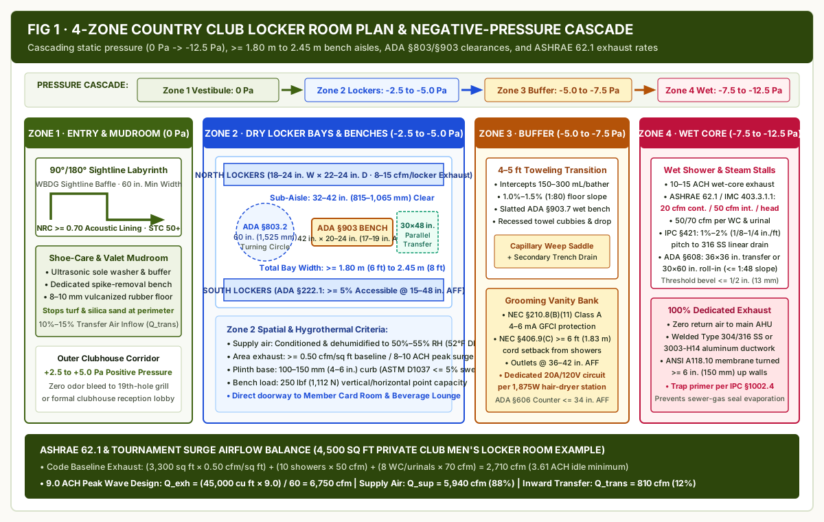
Consider a 4,500 sq ft (418 m²) Private Country Club Men’s Locker Room with a 10.0 ft (3.05 m) ceiling height (Total Volume = 45,000 cu ft), partitioned into 3,300 sq ft of dry locker bays, grooming vanities, and card lounge (Zone 1 + Zone 2 + Zone 3) containing 250 full-tier wood lockers, and a 1,200 sq ft wet shower and sanitary core (Zone 4) containing 10 shower heads and 8 water closets/urinals:
- Step 1 — Code-Minimum Baseline Exhaust (
Q_code_cfm, Off-Peak Idle Mode):Dry Locker Area Exhaust = 3,300 sq ft * 0.50 cfm/sq ft = 1,650 cfmShower Fixture Exhaust (Peak Demand Factor) = 10 shower heads * 50 cfm = 500 cfm(or200 cfmcontinuous idle)Toilet & Urinal Exhaust = 8 fixtures * 70 cfm = 560 cfm(or400 cfmcontinuous idle)Total Code-Minimum Peak Exhaust (Q_code_cfm) = 1,650 + 500 + 560 = 2,710 cfm (1,279 L/s), corresponding to(2,710 * 60) / 45,000 = 3.61 ACH.
- Step 2 — Tournament Surge Exhaust (
Q_surge_cfmat8.2 ACHDry /12.5 ACHWet =9.33 ACHComposite, or9.0 ACHUniform Target):- Sizing for a uniform
9.0 ACHcomposite surge target (6,750 cfmtotal):Zone 2 + Zone 3 Locker Plenum & Vanity Extraction (8.2 ACH) = (3,300 sq ft * 10 ft * 8.18 ACH) / 60 = 4,500 cfm(or3,750 cfmat6.82 ACHdry +3,000 cfmat15.0 ACHwet core =6,750 cfm[3,186 L/s] total exhaust).- Partitioning the
3,750 cfmdry-zone exhaust across250 full-tier lockersextracts12.0 cfm per locker(3,000 cfmtotal through active cabinet crown plenums) plus750 cfmthrough grooming vanity and shoe-care vestibule grilles.
- Sizing for a uniform
- Step 3 — Supply Makeup & Cascading Negative Pressure Balance (
12%Transfer Deficit):- Setting
f_deficit = 0.12(12%negative offset):Direct Conditioned Supply Air (Q_sup_cfm) = 6,750 cfm * 0.88 = 5,940 cfm (2,803 L/s)delivered exclusively into Zone 2 (Dry Locker Bays & Lounge) via low-velocity ceiling diffusers (NC <= 30).Inward Transfer Air (Q_trans_cfm) = 6,750 - 5,940 = 810 cfm (382 L/s)drawn inward from the outer clubhouse corridor (+2.5 to +5.0 Pa) through the Zone 1 Sightline-Baffled Entry Labyrinth (0 Paentry reference ->-2.5 to -5.0 Pain Zone 2 ->-5.0 to -7.5 Pain Zone 3 ->-7.5 to -12.5 Pain Zone 4).
- Setting
- Step 4 — Latent Dehumidification Coil Sizing (
50%–55% RHEnvelope):- During a post-round surge with
10 showersrunning (10 * 450 gr/min = 4,500 gr/min) and80 occupantsdressing (80 * 55 gr/min = 4,400 gr/min), internal latent moisture generation equals8,900 gr/min(76.3 lb/hrof water vapor). - To absorb
8,900 gr/minwhile holding the dry locker bays at73°F(22.8°C) and50% RH(60 grains/lbdry air, dew point53.5°F[11.9°C]), the Dedicated Outdoor Air System (DOAS) or dehumidification AHU must cool the5,940 cfmsupply stream to a leaving coil dew point of48°F to 51°F(8.9°C to 10.6°C,50 to 55 grains/lb) followed by hot-gas reheat (or wrap-around heat-pipe recovery) to deliver neutral70°F to 72°F(21.1°C to 22.2°C) dry air without overcooling bare-skinned bathers.
- During a post-round surge with
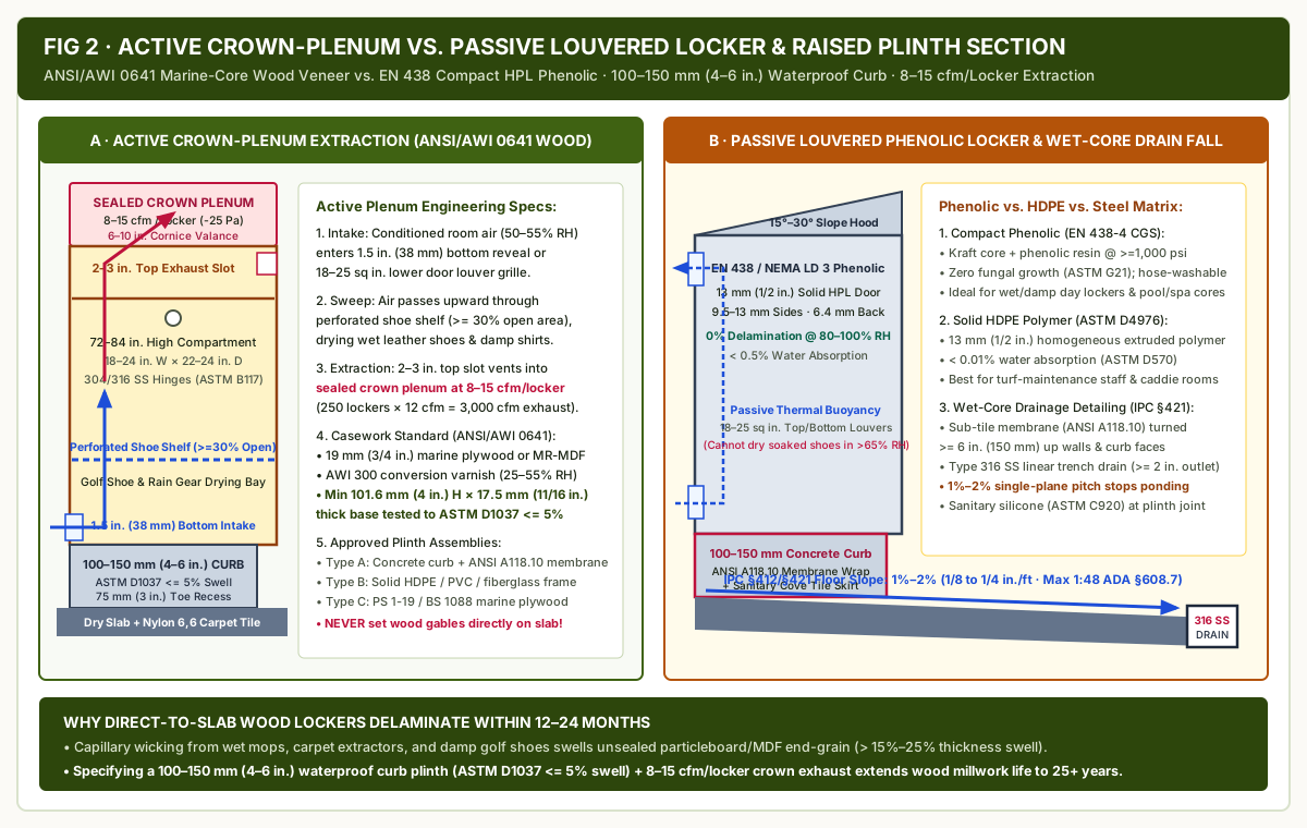
Active Crown-Plenum Extraction vs. Passive Louvered Locker Ventilation
In a humid golf environment, room-level air changes alone cannot dry the interior of a 24 in. deep wooden locker where wet leather golf shoes, sweaty hats, and damp rain jackets are shut behind a solid or lightly louvered door. Specifiers must select between two cabinet ventilation architectures:
- Passive Louvered / Undercut Door Convection (
Light-Duty / Dry-Climate Baseline): Relies on natural thermal buoyancy through a minimum18 to 25 sq in.(116 to 161 cm²) of free open louver or perforation area at both the bottom and top of the locker door (or a1.0 to 1.5 in.[25 to 38 mm] full-width recessed reveal undercut at the bottom and top of solid hardwood doors). Passive ventilation carries zero static pressure differential across the cabinet (< 0.5 Pa); when ambient room humidity exceeds55% to 60% RH, air velocity inside the locker drops below5 fpm(0.025 m/s), leaving wet golf shoes damp for24 to 36 hours. - Active Negative-Pressure Crown-Plenum Extraction (
Country Club & Tournament Standard): Converts every member locker into an active drying chimney connected to the room’s exhaust ductwork:- Bottom Air Intake: Conditioned, dehumidified room air (
50%–55% RH) enters at the base of the locker door through a1.5 in.(38 mm) concealed bottom door undercut or a louvered toe-kick grille providing>= 22 sq in.(142 cm²) of free area. - Perforated Internal Shoe & Garment Shelves: The lower shoe-compartment divider and upper hat shelf are fabricated with CNC-routed slots or stainless steel wire mesh providing
>= 30% to 40%net free open area so rising air sweeps directly across damp shoe soles and leather uppers. - Top Cabinet Exhaust Slot & Balancing Damper: At the top rear or ceiling of each locker compartment, a
2.0 × 8.0 in.(50 × 200 mm) adjustable exhaust slot opens into a continuous, sealed 18-gauge galvanized/aluminum sheet-metal or solid phenolic crown plenum concealed behind the6 to 10 in.(150 to 255 mm) architectural wood cornice valance. - Extraction Rate (
8 to 15 cfmper Full-Tier Locker): The crown plenum operates at-15 to -25 Painternal duct static pressure, pulling8 to 15 cfm(3.8 to 7.1 L/s) of air continuously through each locker and discharging 100% of the moist, odor-laden exhaust air to the roof (or via an enthalpy wheel / run-around coil energy recovery loop with zero cross-leakage).
- Bottom Air Intake: Conditioned, dehumidified room air (
- Rule of Thumb (Active Locker Plenum Extraction): If golfers store golf shoes and rain gear overnight inside full-tier wood lockers, passive door louvers alone cannot prevent musty leather odors; specify active crown-plenum extraction at
10 to 12 cfm per lockerpaired with a>= 30%open perforated shoe shelf and a50%–55% RHDOAS supply system.
2. Country Club Changing Room Layout and Locker Room Benches: Spatial Zoning, >= 1.8 m Aisles, and ADA §803/§903 Geometry
Key takeaway: Organize the country club changing room layout into a strict four-zone progression (Spike Vestibule -> Dry Locker Alcoves -> Toweling/Vanity Buffer -> Wet Shower Core), frame locker bays at >= 1.80 m (6.0 ft) to 2.45 m (8.0 ft) clear width (2.75 to 3.20 m for back-to-back double benches), and engineer locker room benches to 2010 ADA Standards §803.4 and §903 (42 in. min × 20–24 in. deep at 17–19 in. AFF, 250 lbf structural capacity, 30 × 48 in. parallel end transfer space, and 60 in. turning circles).
The Four-Zone Country Club Spatial Progression
As programmed in CED Engineering Course A03-005 (An Introduction to Golf Clubhouse Design) and the WBDG Locker/Shower Room guide, an 18-hole daily-fee clubhouse allocates 1,500 to 3,000 sq ft (139 to 279 m²) to changing facilities, whereas a private country club allocates 6,000 to 12,000+ sq ft (557 to 1,115+ m²) (rising to 12,000 to 20,000+ sq ft at championship venues). To prevent spiked shoes from contaminating wet barefoot tiles and shower water from soaking dry carpets, the floor plan must enforce four sequential zones:
- Zone 1 — Sightline-Baffled Entry Labyrinth & Spike/Shoe-Care Vestibule (
0 Pa Reference Boundary):- WBDG Sightline & Acoustic Labyrinth: Per WBDG privacy criteria, the locker room entrance must use a doorless
90°or180°dog-leg acoustic vestibule (or a double-door vestibule with a>= 48 in.[1,220 mm] clear distance between door swings perADA §404.2.6) that blocks any direct line of sight from public clubhouse corridors into dressing areas while maintainingSTC 50+wall isolation andNRC >= 0.70washable ceiling absorption. - Attendant Valet Counter & Spike-Change Bench: Immediately after crossing the exterior boot-wash and walk-off mat sequence detailed in clubhouse walls and floors where mud meets the building, golfers step onto
8 to 10 mmvulcanized rubber flooring in front of the Locker Room Steward / Valet Counter. Players sit on a dedicated spike-removal bench to exchange cleated golf shoes for clean street footwear or shower sandals and hand dirty shoes to the attendant for ultrasonic sole washing, drying, and waxing before entering the carpeted locker bays.
- WBDG Sightline & Acoustic Labyrinth: Per WBDG privacy criteria, the locker room entrance must use a doorless
- Zone 2 — Dry Carpeted Locker Alcoves & Member Lounge (
-2.5 to -5.0 Pa):- Instead of long, noisy institutional corridor rows, country club lockers are grouped into U-shaped or H-shaped semi-private alcove bays of
8 to 16 lockers per bay, carpeted in solution-dyed nylon 6,6 cut-pile modular tiles with an impervious moisture-barrier cushion backing. - Each alcove centers on fixed or integral locker room benches and opens onto the private Member Card Room, Lounge & Wet Bar, allowing members to watch tournament coverage or dine in casual post-round attire without entering formal clubhouse dining rooms.
- Instead of long, noisy institutional corridor rows, country club lockers are grouped into U-shaped or H-shaped semi-private alcove bays of
- Zone 3 — Toweling Drying Buffer & Grooming Vanity Alcove (
-5.0 to -7.5 Pa):- A
4.0 to 5.0 ft(1.22 to 1.52 m) deep intermediate drying transition and dry grooming vanity bank separating the carpeted locker bays from the wet shower stalls.
- A
- Zone 4 — Wet Shower, Steam/Sauna & Sanitary Core (
-7.5 to -12.5 Pa):- The deeply negative-pressurized barefoot wet core housing individual shower compartments, steam/sauna rooms, water closets, and urinals over sloped waterproofed slabs.
Locker Bay Aisle Widths and Bench Clearance Kinematics
The most common spatial defect in a country club changing room layout is under-sizing the clear distance between facing locker banks and central locker room benches. To calculate the minimum functional bay width, architects must sum four simultaneous physical envelopes:
- Open Locker Door Swing (
D_door):18 to 24 in.(455 to 610 mm) for a full-tier country club locker door open at90°. - Seated Player Dressing Envelope (
E_seated):24 to 30 in.(610 to 760 mm) measured from the front edge of the bench seat to the forward-leaning head/shoulders of a golfer tying golf shoes or pulling on a sweater (plus16 to 24 in.[405 to 610 mm] of bench seat depth). - Pedestrian / Garment-Bag Bypass (
W_pass) or Wheelchair Passage (ADA §403 / §304):30 to 36 in.(760 to 915 mm) minimum dynamic walking width for a member carrying a travel bag (36 in.[915 mm] minimum clear accessible route;60 in.[1,525 mm] wheelchair360°turning diameter perADA §803.2).
Single-Loaded Bay Width (W_single) = D_door + max(E_seated, 30 in. ADA clear space) + W_pass >= 72 in. (1.80 m)
Double-Loaded Fixed-Island Bay Width (W_island) = (2 * W_sub_aisle) + W_bench >= 84 to 96 in. (2.15 to 2.45 m)
Championship Back-to-Back Bench Bay Width (W_double) = (2 * W_sub_aisle) + W_double_bench >= 108 to 126 in. (2.75 to 3.20 m)| Locker Alcove Configuration | Minimum Clear Width (Locker Face to Wall / Locker Face) | Sub-Aisle & Bench Dimensional Breakdown | ADA §803 / §903 Compliance & Surge Throughput Rating |
|---|---|---|---|
| Type 1: Single-Loaded Locker Row + Opposite Wall Bench | >= 1.80 m (6.0 ft / 72 in.) clear width |
18–24 in. (455–610 mm) door swing + 30 in. (760 mm) circulation/transfer zone + 20–24 in. (510–610 mm) wall-affixed bench |
Full 60 in. (1,525 mm) wheelchair turning circle; ideal for narrow structural bays, corridors, and accessible end-bays. |
| Type 2: Double-Loaded Alcove with Pull-Out / Cantilevered Drawer Benches | 1.80 to 2.15 m (6.0 to 7.0 ft / 72 to 84 in.) face-to-face |
Two 16–18 in. (405–455 mm) extended lower-cabinet bench drawers + 36–48 in. (915–1,220 mm) central aisle between facing knees |
When bench drawers retract into the 18 in. high base plinth, leaves an unobstructed 72–84 in. wheelchair turning bay; requires at least one fixed ADA §903 bench per room. |
| Type 3: Double-Loaded Alcove with Fixed Single Island Bench | 2.15 to 2.45 m (7.0 to 8.0 ft / 84 to 96 in.) face-to-face (>= 1.80 m net aisle sum) |
32–38 in. (815–965 mm) Left Sub-Aisle + 18–24 in. (455–610 mm) Fixed Pedestal Bench + 32–38 in. (815–965 mm) Right Sub-Aisle |
Standard private country club 8-to-12-locker alcove; provide a 60 in. (1,525 mm) turning circle at the open alcove entrance or end-bay. |
| Type 4: Championship Double-Loaded Bay with Back-to-Back Bench + Backrest | 2.75 to 3.20 m (9.0 to 10.5 ft / 108 to 126 in.) face-to-face |
36–42 in. (915–1,065 mm) Left Sub-Aisle + 36–42 in. (915–1,065 mm) Double Bench with Center Backrest + 36–42 in. (915–1,065 mm) Right Sub-Aisle |
absorbs 144-player shotgun waves without door-to-back collisions; both sub-aisles provide full 36–42 in. ADA wheelchair passage simultaneously. |
2010 ADA Standards Sections 222, 803, and 903: Accessible Lockers & Locker Room Benches
Under the 2010 ADA Standards for Accessible Design (Sections 222, 803, and 903) and the U.S. Access Board Chapter 10 Guide: Sports Facilities, every locker room, dressing room, and wet shower area must comply with mandatory scoping and dimensional rules for both lockers and locker room benches:
- Accessible Locker Scoping & Reach Ranges (
ADA §222.1,§308,§309):- 5% Minimum per Locker Type: Where lockers are provided, at least
5%(and no fewer than1) of each locker type (full-tier member lockers, half-tier guest lockers, box valuables lockers) must be accessible and dispersed along an accessible route. - Shelf, Hook & Latch Reach Height (
ADA §308): Coat hooks, shoe shelves, and door handles in accessible lockers must be mounted between15 in.(380 mm) minimum and48 in.(1,220 mm) maximum above the finished floor (AFF) for an unobstructed forward or parallel side reach. Where a fixed bench or extended base creates an obstruction deeper than10 in.(255 mm) up to24 in.(610 mm), maximum side-reach height drops to46 in.(1,170 mm) AFF, and minimum low reach rises to20 in.(510 mm) AFF. - One-Hand Operable Hardware (
ADA §309.4): Locks (RFID proximity fobs, push-button keypad locks, or lever latches) and pulls must operate with one hand, without tight grasping, pinching, or twisting of the wrist, under<= 5 lbf(22.2 N) of force. - Clear Floor Space (
ADA §305): A30 in. × 48 in.(760 × 1,220 mm) clear floor space must sit in front of each accessible locker, positioned completely clear of the90°open locker door swing.
- 5% Minimum per Locker Type: Where lockers are provided, at least
- Mandatory Six-Point Specification for Accessible Locker Room Benches (
ADA §803.4&§903):- Seat Length & Depth (
ADA §903.3): The bench must provide a clear seat surface42 in.(1,065 mm) minimum long by20 in.(510 mm) minimum to24 in.(610 mm) maximum deep. Do not exceed24 in.seat depth on an ADA bench; a deeper seat prevents a seated wheelchair user from reaching the rear wall or backrest for trunk stability. - Seat Mounting Height (
ADA §903.5): The top of the bench seat surface must sit at17 in.(430 mm) minimum to19 in.(485 mm) maximum AFF to match standard wheelchair seat cushion heights for level lateral transfers. - Continuous Back Support (
ADA §903.4): The bench must be mounted flush against a structural wall or equipped with an integral structural backrest measuring42 in.(1,065 mm) minimum long, starting no more than2.0 in.(51 mm) above the seat surface and extending to at least18 in.(455 mm) above the seat surface, set within2.0 in.(51 mm) horizontally of the rear seat edge. - Parallel Wheelchair Transfer Space (
ADA §903.2&§305): An unobstructed30 in. × 48 in.(760 × 1,220 mm) clear floor space must be positioned at the end of the bench, with its48 in.long axis aligned parallel to the20–24 in.short axis of the bench. This geometry allows a wheelchair user to pull up flush alongside the end of the bench and execute a side/diagonal pivot transfer onto the seat. While the room’s60 in.(1,525 mm) turning circle (ADA §803.2) may overlap the bench transfer space, no door may swing into the30 × 48 in.bench transfer space (ADA §803.3). - Structural Point-Load Resistance (
ADA §903.6): The bench top, backrest, and cast-metal/steel floor pedestals or concealed wall brackets must support a250 lbf(1,112 N) vertical or horizontal force applied at any point without permanent deflection or anchor failure. - Wet-Location Non-Ponding Seat Construction (
ADA §903.7): Where locker room benches are installed in wet shower cores (Zone 4), toweling buffers (Zone 3), or steam/sauna anterooms, the seat must be slip-resistant and engineered not to accumulate standing water—specified as1.5 to 2.5 in.(38 to 64 mm) wide quarter-sawn teak/ipe hardwood slats or13 to 19 mm(1/2 to 3/4 in.) solid compact phenolic slats spaced with6 to 10 mm(1/4 to 3/8 in.) open drainage slots over aType 316stainless steel frame.
- Seat Length & Depth (
3. Locker Cabinet Materials and Raised Plinth Detailing: ANSI/AWI 0641 Wood Veneer vs. Solid Phenolic on 100–150 mm Curbs
Key takeaway: Isolate all locker cabinets from floor moisture on a 100 to 150 mm (4 to 6 in.) waterproof concrete, solid HDPE/PVC, or marine-plywood curb plinth meeting ANSI/AWI 0641 (>= 17.5 mm thickness and ASTM D1037 <= 5% 24-hour water-soak thickness swell), restrict AWI 300 hardwood veneer lockers to climate-controlled dry bays (25%–55% RH), and specify EN 438 / NEMA LD 3 solid compact phenolic (0% delamination) in damp or wet zones.
Why Direct-to-Slab Lockers Delaminate—and How to Engineer the 100–150 mm Plinth
When locker side gables (19 mm [3/4 in.] wood veneer panels) extend directly to the finished floor slab, capillary suction draws moisture from wet string mops, rotary carpet-extraction machines, damp golf umbrellas, and concrete slab vapor transmission straight into the bottom end-grain. Standard industrial particleboard (ANSI A208.1 M-2) and unrated medium-density fiberboard (ANSI A208.2) exhibit 12% to 25% thickness swelling after a 24-hour water soak (ASTM D1037), splitting face veneers, popping cam-lock joints, and growing black mold along the floor line within two golf seasons.
Under the Architectural Woodwork Institute (AWI) ANSI/AWI 0641 Architectural Wood Casework Standard, moisture-resistant locker base assemblies must satisfy three strict structural and material requirements:
- Raised Curb / Plinth Elevation (
100 to 150 mm/4.0 to 6.0 in.AFF): ANSI/AWI 0641 mandates a minimum finished installed height of101.6 mm(4.0 in.) for casework toe-kick bases. In golf and country club locker rooms, specifiers standardize the plinth height at100 to 150 mm(4.0 to 6.0 in.) AFF with a75 mm(3.0 in.) horizontal toe-kick recess along the locker face so4 in.(100 mm) sanitary cove base moulding, wet mops, and commercial carpet extractors never strike the finished cabinet doors. - Minimum Structural Thickness &
ASTM D1037 <= 5%Swell Limit: ANSI/AWI 0641 requires toe-kick sleep frames to be fabricated from material at least17.5 mm(0.688 in./11/16 in.) thick (typically 19 mm [3/4 in.]). When specified as a moisture-resistant base, the substrate must be tested in accordance with ASTM D1037 and exhibit a 24-hour water-soak thickness swell factor of<= 5.0%. - Three Approved Country Club Plinth Assemblies:
- Assembly A — Cast-in-Place Concrete Housekeeping Curb (
Wet/Transition & Heavy Washdown Zones): A100 to 150 mm(4 to 6 in.) high ×480 to 560 mm(19 to 22 in.) deep concrete curb doweled or cast monolithically with the structural floor slab, wrapped continuously in a bonded liquid/sheet waterproofing membrane (ANSI A118.10), and faced with coved unglazed porcelain tile or10 mmvulcanized rubber. - Assembly B — Solid HDPE / Cellular PVC or Pultruded Fiberglass Plinth (
Dry Carpeted & Damp Bays): An engineered ladder frame constructed from19 mm(3/4 in.) solid high-density polyethylene (HDPE), cellular PVC, or phenolic composite (0.0%water absorption) onType 304/316stainless steel adjustable leveling legs, faced with a removable moisture-proof toe-kick fascia sealed to the floor with ASTM C920 Class 25 sanitary mildew-resistant silicone. - Assembly C — Marine-Grade Plywood Plinth (
AWI 300 Custom Dry Bays):19 mm(3/4 in.) Douglas Fir or Okoume Marine-Grade Plywood (PS 1-19orBS 1088) bonded with100%waterproof phenolic resin adhesive and zero core voids, encapsulated on all six faces (including field-cut notches) with two coats of catalyzed polyurethane sealer prior to setting the upper locker boxes.
- Assembly A — Cast-in-Place Concrete Housekeeping Curb (
Locker Cabinet Material Comparison: ANSI/AWI 0641 Wood Veneer vs. Solid Phenolic vs. HDPE vs. Steel
Selecting the cabinet body material requires matching the substrate’s hygrothermal tolerance to the zone’s relative humidity and cleaning regimen:
| Cabinet Material System | Core, Panel Thickness & Finish Standard | Water Absorption & Relative Humidity Envelope | Hardware & Fastener Specification | Optimal Country Club Zone & Service Life |
|---|---|---|---|---|
Architectural Hardwood & Marine-Core Veneer (ANSI/AWI 0641 / AWI 300) |
19 mm (3/4 in.) veneer-core hardwood plywood (ANSI/HPVA HP-1) or MR-MDF (ASTM D1037 <= 5% swell); White Oak, Mahogany, Sapele, or Walnut veneer with AWI 300 catalyzed conversion varnish. |
Requires controlled indoor HVAC envelope of 25% to 55% RH (AWI 200); must sit on a 100–150 mm waterproof plinth with active 8–15 cfm crown exhaust. |
Type 304/316 stainless steel or PVD brass concealed 110°–165° soft-close European cup hinges (ASTM B117 >= 240 hr salt spray). |
Zone 2 Dry Member Locker Bays & Sanctuary Lounge; 25 to 35+ year service life when RH is held <= 55%. |
Solid Compact Phenolic (HPL) (EN 438-4 CGS / NEMA LD 3) |
Homogeneous kraft core impregnated with phenolic resin and melamine decorative surface cured at >= 1,000 psi & 300°F: 13 mm (1/2 in.) doors, 9.5–13 mm (3/8–1/2 in.) sides/tops/shelves, 6.4 mm (1/4 in.) back. |
0% delamination; mass water absorption < 0.5% to 1.0% (EN 438-2); withstands continuous 80% to 100% RH, steam, and direct hose washdown (ASTM G21 zero fungal growth). |
Thru-bolted Type 316 stainless steel barrel or continuous piano hinges and tamper-resistant Torx fasteners. |
Zone 3/4 Wet-Transition Lockers, pool/fitness/spa changing rooms, day-guest lockers, and caddie quarters; 25 to 30+ year life. |
Solid High-Density Polyethylene (HDPE) (ASTM D4976 Polymer) |
13 mm (1/2 in.) homogeneous extruded high-density polyethylene panels throughout doors, sides, tops, and bottoms with integral routed ventilation slots. |
< 0.01% water absorption (ASTM D570); immune to rust, pool chlorine, salt air, and quaternary ammonium disinfectants; high dent resistance. |
Full-height heavy-duty Type 304/316 stainless steel piano hinges and continuous HDPE/stainless latch bars. |
Back-of-house turfgrass maintenance staff lockers, municipal wet cores, and junior swim changing rooms; 20 to 30 year life. |
Powder-Coated Galvannealed / Stainless Steel (ASTM A653 / A240) |
16-gauge (1.5 mm) doors and 18-gauge (1.2 mm) bodies in G60/G90 galvannealed steel or Type 304 stainless steel with 1.5–2.0 mil antimicrobial TGIC polyester powder coat. |
Zero core water absorption, but cold-rolled carbon steel rusts rapidly at spot-welded bottom seams if RH > 60% or exposed to turf fertilizers without galvannealing. |
Stainless steel pin hinges or recessed multi-point cremone latches with rubber acoustic door bumpers. | Ventilated metal-mesh golf gear lockers, employee changing rooms, and dry utility corridors; 15 to 25 year life. |
Full-Tier Country Club Golf Locker Compartment Dimensions
Unlike standard 12 × 12 in. (305 × 305 mm) athletic gym box lockers, a country club member locker must accommodate two to three pairs of golf shoes on a ventilated rack, a tailored blazer or suit jacket on a full-width wooden hanger (17 to 19 in. wide), rain gear, a lockable valuables security box, and a lower footstool or pull-out drawer:
- Private Country Club Full-Tier Member Locker:
18 to 24 in.(455 to 610 mm) wide ×22 to 24 in.(560 to 610 mm) deep ×72 to 84 in.(1,830 to 2,135 mm) clear box height. Mounted atop a4 to 6 in.(100 to 150 mm) waterproof plinth and topped by a6 to 10 in.(150 to 255 mm) exhaust plenum cornice, the total installed millwork height reaches82 to 100 in.(2.08 to 2.54 m). Note that a22 to 24 in.(560 to 610 mm) cabinet depth is critical: a men’s size44Rblazer on a contoured hardwood hanger measures19.5 in.(495 mm) shoulder-to-shoulder; placing it inside a shallow18 in.(455 mm) gym locker crushes the jacket sleeve against the door face and blocks vertical airflow. - Tournament Guest / Daily-Fee Day Locker:
15 to 18 in.(380 to 455 mm) wide ×20 to 22 in.(510 to 560 mm) deep ×36 to 72 in.(915 to 1,830 mm) high (configured as single-tier full-height or double-tier36 in.half-height compartments).
4. Wet-Zone Separation, Shower Drainage Falls (IPC §412/§421), and NEC Article 210.8(B) GFCI Vanity Layout
Key takeaway: Stop wet-to-dry water migration with a two-stage wet boundary—an IPC §421 shower receptor pitched at 1% to 2% (1/8 to 1/4 in./ft, capped at 1:48 [2.08%] in ADA §608.7 stalls) to a Type 316 stainless linear trench drain, followed by a 4 to 5 ft (1.2 to 1.5 m) sloped toweling buffer—and wire grooming vanities with NEC §210.8(B)(11) Class A 4–6 mA GFCI outlets mounted at 36 to 42 in. AFF, set back >= 6 ft (1.83 m) from shower edges on dedicated 20A / 120V circuits per hair dryer.
Stopping the 6-to-12-Liter Carryout Flood: Two-Stage Shower & Toweling Drainage (IPC §412 / §421 & ADA §608)
When a bather steps out of a shower stall without toweling dry inside a dedicated buffer zone, water clinging to skin, hair, and rubber sandals averages 150 to 300 mL (5 to 10 fl oz) per person. Across a 40-player post-round shower wave, 6.0 to 12.0 liters (1.6 to 3.2 gallons) of soapy water is carried directly out of the stalls. As emphasized in the UK Health and Safety Executive (HSE) Slips and Trips guidance and our parent inspection guide changing rooms: benches, hooks and water on the tile, allowing that water to cross the threshold onto smooth tile or dry locker room carpet creates an immediate barefoot hydroplaning hazard and rots subfloor adhesives.
To contain 100% of shower spray and bather carryout water inside the wet core, specifications must enforce a two-stage wet-to-dry floor architecture governed by the International Plumbing Code (IPC §412 Floor Drains and §421 Showers) and the U.S. Access Board ADA Chapter 6 Guide: Bathing Rooms and Shower Compartments (ADA §608):
- Stage 1 — Shower Stall Receptor & Linear Trench Drain Interception (
Zone 4,IPC §421.3 / §421.5&ADA §608.7):- Compartment Dimensions: Standard private country club shower stalls measure
42 × 48 in.(1,065 × 1,220 mm) to48 × 60 in.(1,220 × 1,525 mm) clear inside (exceeding theIPC §421.4minimum of900 sq in.[0.58 m²] with a30 in.[760 mm] minimum circle). Accessible compartments must comply withADA §608.2.1Transfer-Type Stalls (exactly 36 × 36 in.[915 × 915 mm] clear inside dimension with a folding seat and36 × 48 in.perpendicular entry clearance) orADA §608.2.2Standard Roll-In Stalls (30 in.[760 mm] min deep ×60 in.[1,525 mm] min wide with a30 × 60 in.entrance clearance). - Floor Slope Tolerance (
1% to 2%/1/8 to 1/4 in. per ft): UnderIPC §421.5.2.1, the waterproof subfloor liner (ANSI A118.10bonded sheet or liquid membrane turned up perimeter walls>= 6.0 in.[150 mm] and>= 2.0 in.[51 mm] above the drain/curb rim) must pitch toward the waste outlet at1% to 2%(1/8 in. to 1/4 in. per foot, or1:96 to 1:48). Crucially, inside accessible roll-in and transfer shower stalls,ADA §608.7caps the maximum finished floor slope at1:48(2.08%/1/4 in. per foot) in any direction so wheelchair casters do not drift. Setting the design specification at1.5% to 2.0%(3/16 to 1/4 in. per foot, or1:65 to 1:50) satisfies bothIPCpositive drainage and theADA 1:48ceiling simultaneously. - Single-Plane Pitch to a
Type 316Stainless Linear Trench Drain: Instead of four-way bowl slopes that force small mosaic tiles and create uneven wheelchair footing, pitch large-format textured unglazed porcelain tile (DIN 51097 Class B/C,ANSI A326.3 wet DCOF >= 0.50grouted with100%solids epoxy perANSI A118.3) in a single uniform plane (1.5% to 2.0%) toward aType 316stainless steel linear slot/trench drain (>= 2.0 in.[51 mm] waste outlet perIPC §421.3with an automatic trap-seal primer perIPC §1002.4). In roll-in accessible stalls (ADA §608.5), mount the linear trench drain either along the back wall (pitching the floor away from the threshold) or directly along the entrance threshold line beneath a flush<= 1/2 in.(13 mm) beveled curb (ADA §608.7).
- Compartment Dimensions: Standard private country club shower stalls measure
- Stage 2 — Dedicated 4-to-5-Foot Toweling & Drying Buffer Alcove (
Zone 3):- Never open a shower stall door directly onto a carpeted locker aisle. Immediately outside each private shower stall (or serving a cluster of
4 to 6stalls), construct a4.0 to 5.0 ft(1.22 to 1.52 m) deep toweling alcove equipped with recessed clean-towel cubbies (15 to 48 in.AFF), dual robe hooks (48 in.max AFF for accessible hooks perADA §308), a soiled-linen drop chute, and a wet-ratedADA §903.7slatted teak or solid phenolic drying bench. - Pitch the toweling alcove tile floor at
1.0% to 1.5%(1/8 in. per foot/1:80) back toward the shower threshold trench drain or a dedicated secondary floor drain. - At the outer doorway separating the Zone 3 Toweling/Vanity Buffer from the Zone 2 Dry Carpeted Locker Bays, install a flush solid-surface or granite threshold saddle (
<= 1/4 in.vertical lip or1:2bevel up to1/2 in.) anchored over a sub-tile stainless steel capillary break angle so sub-surface moisture in the mortar bed cannot wick laterally into the carpet cushion.
- Never open a shower stall door directly onto a carpeted locker aisle. Immediately outside each private shower stall (or serving a cluster of
NFPA 70 (NEC) Article 210.8(B) & 406.9 Grooming Vanity Electrical Engineering
Country club grooming vanities concentrate high-wattage personal care appliances—1,500 to 1,875W commercial salon hair dryers, electric shavers, hot lather dispensers, and curling/flat irons—within steps of barefoot shower bathers and running lavatory faucets. Electrical specifications must enforce four provisions of NFPA 70: National Electrical Code (NEC) Articles 210.8(B) and 406.9 alongside 2010 ADA Standards §606 and §308:
- Universal Class A GFCI Protection Across All Locker Room Receptacles (
NEC §210.8(B)):- Commercial Locker Room Mandate (
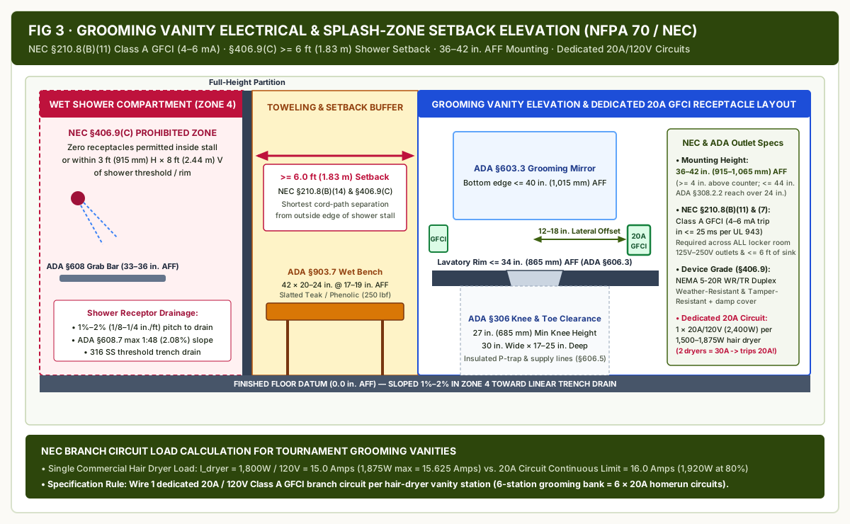
NEC §210.8(B)(11)): Every125V through 250Vsingle-phase receptacle (rated <= 150V to groundand<= 50A) installed anywhere inside locker rooms with associated showering facilities must be protected by a Class A Ground-Fault Circuit-Interrupter (GFCI) that trips at a fault current of4 to 6 mAwithin0.025 seconds(25 ms) perUL 943. This rule applies to every outlet in the locker room—including shoe-polishing buffers in Zone 1, phone-charging receptacles inside dry Zone 2 wood lockers, and grooming vanities in Zone 3. - Sink & Shower 6-Foot Cord-Path Rule (
NEC §210.8(B)(7), (14) & (15)): Class A GFCI protection is independently required for all receptacles installed within6.0 ft(1.83 m) of the outside edge of any sink basin (§210.8(B)(7)), within6.0 ft(1.83 m) of the outside edge of any shower stall or bathtub (§210.8(B)(14)), and in all indoor damp or wet locations (§210.8(B)(15)), measured along the shortest unobstructed path a flexible appliance cord would follow without piercing a wall, doorway, or fixed partition.
- Commercial Locker Room Mandate (
- Shower Splash-Zone Prohibition & >= 1.5–1.8 m Horizontal Vanity Setback (
NEC §406.9(C)):- Under
NEC Section 406.9(C), receptacles are strictly prohibited inside a shower stall or within the3.0 ft(915 mm) horizontal and8.0 ft(2.44 m) vertical zone extending from the shower stall threshold or rim. - In high-humidity country club locker rooms, best-practice MEP engineering places the dry grooming vanity counter in Zone 3 at a minimum
1.5 to 1.8 m(5.0 to 6.0 ft) horizontal splash setback from any shower compartment doorway or threshold, physically separated from Zone 4 by a full-height glass or tiled wing wall so wet bathers cannot touch a live hair dryer while standing on wet shower tile.
- Under
- Ergonomic & ADA Vanity Receptacle Mounting (
36 to 42 in. AFF&12 to 18 in.Lateral Offset):- Under
ADA §606.3, accessible grooming lavatory countertops/rims must be mounted no higher than34 in.(865 mm) AFF with a minimum27 in.(685 mm) high ×30 in.(760 mm) wide ×17 to 25 in.(430 to 635 mm) deep clear knee and toe space underneath (ADA §306, with insulated water supply and drain pipes perADA §606.5) and mirrors mounted with the bottom edge of the reflecting surface at<= 40 in.(1,015 mm) AFF (ADA §603.3). - Under
ADA §308.2.2(Obstructed High Forward Reach), when a user reaches forward over a vanity counter that is20 to 25 in.(510 to 635 mm) deep, the maximum allowable height for an electrical receptacle is44 in.(1,120 mm) AFF. - Mounting commercial heavy-duty Weather-Resistant (
WR) and Tamper-Resistant (TR)20A / 125V(NEMA 5-20R) duplex GFCI receptacles at36 to 42 in.(915 to 1,065 mm) AFF places the outlets2 to 8 in.(50 to 200 mm) above the34 in.countertop splash plane while keeping them comfortably below the44 in.ADA reach ceiling. Offset every receptacle12 to 18 in.(305 to 455 mm) laterally from the sink faucet centerline (never directly behind the faucet spout) and fit receptacles in damp zones with listed weatherproof covers (NEC §406.9(A)).
- Under
- Dedicated
20A / 120VBranch Circuit Sizing per Hair-Dryer Station (Preventing Breaker Trips):- Commercial club and salon handheld hair dryers draw
1,500 to 1,875 Wattsat120V. Daisy-chaining multiple grooming vanity stations onto a single shared20Acircuit is the #1 electrical failure during women’s and men’s tournament shotgun events.
- Commercial club and salon handheld hair dryers draw
Hair Dryer Current Draw (I_dryer_amps) = P_dryer_watts / V_circuit_volts
Maximum Continuous 20A Branch Circuit Load (P_cont_max) = 20A * 120V * 0.80 = 1,920W (16.0A per NEC §210.20)
Maximum Non-Continuous 20A Branch Circuit Load (P_peak_max) = 20A * 120V * 1.00 = 2,400W (20.0A)
Required Dedicated 20A Circuits (N_circuits) = N_active_hair_dryer_stations- Worked Electrical Circuit Load Calculation (6-Station Country Club Grooming Vanity Bank):
- Single
1,800W(1,875Wnominal) Hair Dryer Current:I_dryer = 1,800W / 120V = 15.0 Amps(1,875W / 120V = 15.625 Amps). - Failure Mode (Two Stations Wired on One Shared
20ACircuit): When two golfers switch on1,800Whair dryers simultaneously after a round, combined current reaches15.0A + 15.0A = 30.0 Amps(3,600W), exceeding the20Athermal-magnetic breaker rating by150%and tripping the circuit within seconds. - Engineered Solution: Specify one dedicated
20A / 120V(#12 AWGTHHN/THWN-2 copper in EMT conduit) Class A GFCI branch circuit per hair-dryer grooming station. For a 6-station grooming vanity bank (6 × 1,800W = 10,800 VAtotal connected load =90.0 Ampsat120V, or45.0 Ampsbalanced across a120/208V3-phase or120/240Vsplit-phase subpanel), run six independent20Ahomerun circuits to the local locker room branch panelboard, plus a separate20AGFCI circuit for low-wattage shaver/toothbrush convenience outlets (<= 180 VAeach).
- Single
| Electrical / Plumbing Parameter | Governing Code & Section | Mandatory Engineering Specification | Field Failure Mode if Violated |
|---|---|---|---|
| Locker Room GFCI Protection | NFPA 70 (NEC) §210.8(B)(11) & UL 943 |
Class A GFCI (4–6 mA trip in <= 25 ms) on 100% of 125V–250V (<= 50A) receptacles anywhere in the locker room. |
Lethal ground-fault shock risk to barefoot bathers; fails electrical rough-in and certificate-of-occupancy inspection. |
| Shower Stall & Sink Setback | NEC §210.8(B)(7)/(14) & §406.9(C) |
Zero outlets inside or within 3 ft H × 8 ft V of shower stall; >= 6.0 ft (1.83 m) cord-path separation from shower threshold; 12–18 in. lateral offset from faucet. |
Direct water spray into live `NEMA 5-20R` faceplates causing nuisance GFCI trips and terminal corrosion. |
| Vanity Outlet Mounting Height | 2010 ADA §308.2.2 & §606.3 |
Mount `WR/TR` duplex outlets at 36 to 42 in. (915–1,065 mm) AFF over a <= 34 in. (865 mm) high ADA vanity counter (max 44 in. reach over 20–24 in. depth). |
Outlets mounted at `48 in.` AFF above a `24 in.` deep counter violate federal `ADA §308.2.2` forward-reach limits (`44 in.` max). |
| Hair-Dryer Branch Circuit Capacity | NEC §210.11, §210.20 & §210.23 |
1 dedicated 20A / 120V (2,400W) circuit per hair-dryer station (1,500–1,875W / 12.5–15.6A load) using `#12 AWG` copper conductors. |
Two `1,800W` dryers on a shared `20A` circuit draw `30A` (`3,600W`), tripping breakers during every shotgun tournament wave. |
| Shower Receptor & Toweling Floor Pitch | IPC §412 / §421.5 & ADA §608.7 |
Pitch shower pan/tile at 1.5% to 2.0% (3/16 to 1/4 in./ft, max 1:48 [2.08%] ADA) to a `Type 316 SS` linear trench drain + 4–5 ft toweling buffer at 1.0%–1.5%. |
Slopes `< 1%` pond soapy water; slopes `> 2.08%` (`1:48`) fail ADA wheelchair inspection; missing buffer floods dry carpet with `6–12 L` of water. |
5. On-Site Commissioning & Specifier Verification Checklist
Key takeaway: Verify locker room readiness before tournament play with five quantitative field instruments—a differential micromanometer (-2.5 to -12.5 Pa), a thermo-hygrometer (50%–55% RH), a 4 ft digital spirit level (1.5%–2.0% drain fall), a steel tape measure (>= 1.80 m aisles, 100–150 mm plinths, ADA §903 benches), and a UL 943 GFCI loop/load tester (4–6 mA trip + 20A dedicated circuit verification).
When reviewing architectural/MEP construction documents or commissioning a newly renovated changing facility in coordination with clubhouse design and changing rooms: benches, hooks and water on the tile, record the following ten measurements in writing:
- Cascading Negative Static Pressure Check (
ASHRAE 62.1/WBDG): With all doors in their normal operating position and the HVAC system in active mode, place a digital differential micromanometer hose under the entry vestibule threshold and wet-core doorway. Confirm inward airflow and record-2.5 to -5.0 Pain Zone 2 Dry Locker Bays,-5.0 to -7.5 Pain Zone 3 Toweling/Vanity Buffers, and-7.5 to -12.5 Pain Zone 4 Wet Showers relative to the outer clubhouse corridor (+2.5 to +5.0 Pa). - 8–10 ACH Surge & Active Crown-Plenum Airflow Balance (
TAB Report): Review the Testing, Adjusting, and Balancing (TAB) hood readings to confirm a minimum0.50 cfm/sq ftcontinuous baseline,8 to 10 ACHpeak surge capacity in dry bays,10 to 15 ACH(>= 20/50 cfm per shower head) in wet cores, and8 to 15 cfm per full-tier lockerdrawn through the top cabinet exhaust slots over>= 30%open perforated shoe shelves. - Latent Dehumidification Setpoint (
<= 55% RH): Using a calibrated psychrometer during peak post-round shower operation, verify that the DOAS/reheat coil maintains Zone 2 dry locker bay relative humidity at50% to 55% RH(never exceeding55% RHperAWI 200woodwork limits). - Sightline-Baffled Vestibule & Shoe-Care Mudroom (
Zone 1): Stand in the public clubhouse corridor with any entry doors propped open and confirm zero direct visual sightline into the locker bays (90°/180°acoustic labyrinth with>= 60 in.clear width,STC 50+walls, and8 to 10 mmvulcanized rubber floor at the spike-changing bench). - Locker Bay Clear Aisle Width (
>= 1.80 m to 2.45 m): Measure the clear distance between facing locker doors (>= 1.80 m[72 in.] for single-loaded or pull-out drawer bays;2.15 to 2.45 m[84 to 96 in.] for fixed central island bench bays;2.75 to 3.20 m[108 to 126 in.] for back-to-back double bench bays) and verify32 to 42 in.clear sub-aisles around central benches. - ADA §222 Lockers & §803/§903 Bench Geometry: Verify that
>= 5%of each locker type meets15 to 48 in. AFFreach ranges and<= 5 lbflatch force, and measure the accessible locker room benches:42 in.(1,065 mm) min length ×20 to 24 in.(510 to 610 mm) depth,17 to 19 in.(430 to 485 mm) AFF seat height,42 × 18 in.backrest,30 × 48 in.parallel end transfer space clear of door swings, and60 in.(1,525 mm) turning circle. - 100–150 mm Raised Plinth &
ASTM D1037 <= 5%Submittal: Measure the finished locker curb/plinth height (100 to 150 mm[4 to 6 in.] AFF with a75 mm[3 in.] toe recess), confirm submittals forANSI/AWI 0641moisture-resistant base material (>= 17.5 mmthick,ASTM D1037 <= 5%24-hour swell) or waterproofed concrete/HDPE curbs, and verify continuousASTM C920sanitary silicone perimeter sealing. - Cabinet Substrate & Hardware Corrosion Rating: Confirm
AWI 300conversion-varnished hardwood veneer (18–24 in. W × 22–24 in. D) in dry bays,EN 438-4 / NEMA LD 3solid compact phenolic (13 mmdoors) in wet/damp bays, andType 304/316stainless steel or PVD brass hinges (ASTM B117 >= 240 hr). - Shower Floor Fall (
1.5%–2.0%) & 4–5 ft Toweling Buffer (IPC §421/ADA §608.7): Place a digital inclinometer across the shower stall floor and verify a uniform1.5% to 2.0%(3/16 to 1/4 in./ft) single-plane pitch toward theType 316stainless linear trench drain (strictly<= 2.08%[1:48] inside accessible stalls, with a<= 1/2 in.beveled threshold), backed by a4.0 to 5.0 ft(1.2 to 1.5 m) sloped toweling buffer alcove (1.0%–1.5%pitch) and capillary break saddle before the dry carpet. - NEC §210.8(B) Class A GFCI & Dedicated 20A Hair-Dryer Circuit Test: Plug a
UL 943GFCI tester into every receptacle in the locker room to verify4 to 6 mAClass A trip response, measure>= 6.0 ft(1.83 m) cord-path separation from shower thresholds (NEC §406.9(C)), confirm36 to 42 in. AFFoutlet height over<= 34 in. AFFaccessible vanities, and switch on all1,800Wvanity hair dryers simultaneously for15 minutesto confirm dedicated20A / 120Vbranch circuits hold without tripping.
Method and sources
Mechanical exhaust rates, air-change surge benchmarks, and negative-pressure containment criteria are synthesized from ANSI/ASHRAE Standard 62.1 (Ventilation and Acceptable Indoor Air Quality, Section 6.5 and Table 6-2), the International Mechanical Code (IMC Table 403.3.1.1), and the National Institute of Building Sciences Whole Building Design Guide (WBDG Locker / Shower Room). Federal accessibility dimensions for lockers, turning circles, dressing benches, bathing rooms, and shower stalls follow the U.S. Department of Justice (2010 ADA Standards for Accessible Design, Sections 222, 305, 308, 309, 603, 606, 608, 803, and 903) and the U.S. Access Board Guides (Chapter 6: Bathing Rooms and Shower Compartments and Chapter 10: Sports Facilities). Custom wood locker fabrication, ambient humidity envelopes (25%–55% RH), and moisture-resistant toe-kick plinth standards (>= 101.6 mm height, >= 17.5 mm thickness, ASTM D1037 <= 5% swell) reference the Architectural Woodwork Institute (ANSI/AWI 0641 Architectural Wood Casework and AWI 200/300 Materials Standards). Country club changing room spatial programming and shoe-care vestibule routing cite CED Engineering (An Introduction to Golf Clubhouse Design, Course No. A03-005). Wet-to-dry floor drainage slopes and slip-prevention thresholds reference the International Plumbing Code (IPC Sections 412 and 421) and the UK Health and Safety Executive (HSE Slips and Trips). Ground-fault circuit-interrupter protection, wet/damp splash setbacks, and branch circuit sizing follow the National Fire Protection Association (NFPA 70: National Electrical Code, Articles 210.8(B) and 406.9), all accessed 26 October 2026. Updated October 2026.