Selecting a putting green construction profile requires matching rootzone particle gradation, subsurface drainage geometry, and gravel-to-sand interface physics to local rainfall intensity and subgrade soils. In the USGA putting green construction method, the putting green site is excavated to a depth approximately 16 inches (400 millimeters) below the proposed surface grade, or 18 to 20 inches (450 to 500 mm) when an intermediate layer is necessary. A California method green places 12 inches of sand directly on a trenched subgrade without a gravel blanket; on flat greens (having a general slope of less than 2%), laterals are typically placed at 10-foot intervals, whereas where slopes exceed 2% there are no laterals in the back half. Related course infrastructure specifications are available in our sports facilities engineering archive, including golf course irrigation pressure and uniformity and bunker sand particle size and drainage.
Side-by-Side Engineering Comparison: USGA Two-Tier vs California Method Profiles
Comparing the USGA perched-water-table profile against the University of California unamended sand profile highlights how gravel blanket continuity, rootzone hydraulic conductivity, and subsurface flow-path direction interact across a green cavity.
| Engineering Parameter | USGA Putting Green Profile | California Method Profile |
|---|---|---|
| Cavity Excavation and Rootzone Depth | In the USGA putting green construction method, the putting green site is excavated to a depth approximately 16 inches (400 millimeters) below the proposed surface grade, or 18 to 20 inches (450 to 500 mm) when an intermediate layer is necessary. The USGA rootzone mixture should be spread and uniformly firmed to a 12-inch (300 mm) depth with a tolerance of plus or minus 1 inch (25 mm). | Most University of California greens are graded evenly at the subbase so that they have a 2 to 4 percent slope from back to front, and surface contours do not change the total depth of sand at the highest point more than 3 inches (7.5 cm). In the California method, unamended sand is firmed to a uniform 12-inch depth, and selective placement of 1 to 2 cubic yards of sand for surface contouring may be as much as 3 inches thicker (for a total depth of 15 inches). |
| Gravel Blanket vs Trench-Only Gravel | The entire subgrade is covered with clean, washed crushed stone or pea gravel to a minimum thickness of 4 inches (100 mm), and the surface of the finished gravel layer should be 12 inches (300 mm) below the finished grade (14 to 16 inches or 350 to 400 mm if an intermediate layer is required) and shall conform to the proposed finished grade, plus or minus 1 inch. | In a California green, drainage gravel (1/4-inch diameter pea gravel) is only placed in the trench and is not used as a drainage blanket, and a layer of gravel equal to the pipe diameter should cover the crown of the pipe. |
| Lateral Drain Spacing and Slope | Lateral drainage pipes should be spaced not more than 15 feet (5 meters) apart and have a continuous slope of 0.5 percent or greater to the main drain. | A California method green places 12 inches of sand directly on a trenched subgrade without a gravel blanket; on flat greens (having a general slope of less than 2%), laterals are typically placed at 10-foot intervals, whereas where slopes exceed 2% there are no laterals in the back half. |
| Drainage Flow Path Geometry | At field capacity in a USGA putting green, a perched water table forms at the base of the root zone, and optimally this zone of saturated soil should extend no more than about 6 inches up from the interface. | In a California green with a root zone thickness of 12 inches and a drain line spacing of, say, 18 feet, much of the path length for water flow is directed laterally, whereas in a USGA green all flow paths across the root zone are vertical. |
| Hydraulic Conductivity and Drainage Coefficient | A USGA rootzone mixture shall have physical properties tested per ASTM F1815 meeting the Table 4 recommended ranges of Total Porosity 35%–55%, Air-filled Porosity 15%–30%, Capillary Porosity 15%–25%, and Saturated Hydraulic Conductivity (Ksat) ≥ 6 inches/hour (150 mm/hr.). | Saturated hydraulic conductivity of a root zone mix for a USGA green ranges from 6 to 24 inches per hour (from the 1993 revision), whereas the conductivity of a California green can range from 20 to 60 inches per hour. In Ohio State University Table 4-1, design subsurface drainage coefficients are 1 inch per day for push-up greens and tees, 1 inch per hour for high-sand tees (6 - 8 inch root zone), 2 inches per hour for high-sand greens (California and USGA), and 4 inches per hour for sand bunkers. |
USGA Putting Green Cavity, Subgrade Compaction, and Subsurface Drainage
Preparing a stable putting green cavity prevents differential settlement, perimeter moisture loss, and subsurface ponding beneath the gravel blanket. Cavity walls should be 90 degrees to the cavity floor or steeply sloped, and include the collar area as part of the putting green cavity. If fill soil is used to construct the putting green subgrade, the soil should be placed in 6-inch lifts and compacted to at least 90 percent of minimum standard Proctor density ASTM D698. Unstable putting green subgrades can be placed in 6-inch lifts and recompacted to 90 to 95 percent Proctor density, or stabilized by adding hydrated lime at approximately 2 to 6 percent by weight. USGA perimeter wicking barriers use polyethylene sheeting 6 to 8 mil and usually 18 to 36 inches wide, or an 18-inch-wide, 30-mil-thick material, leaving 4 to 6 inches extending above grade during construction.
Subsurface Trench Dimensions, Pipe Specifications, and Gravel Stability
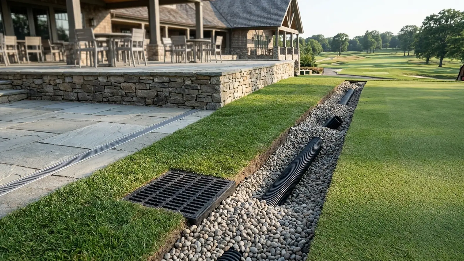
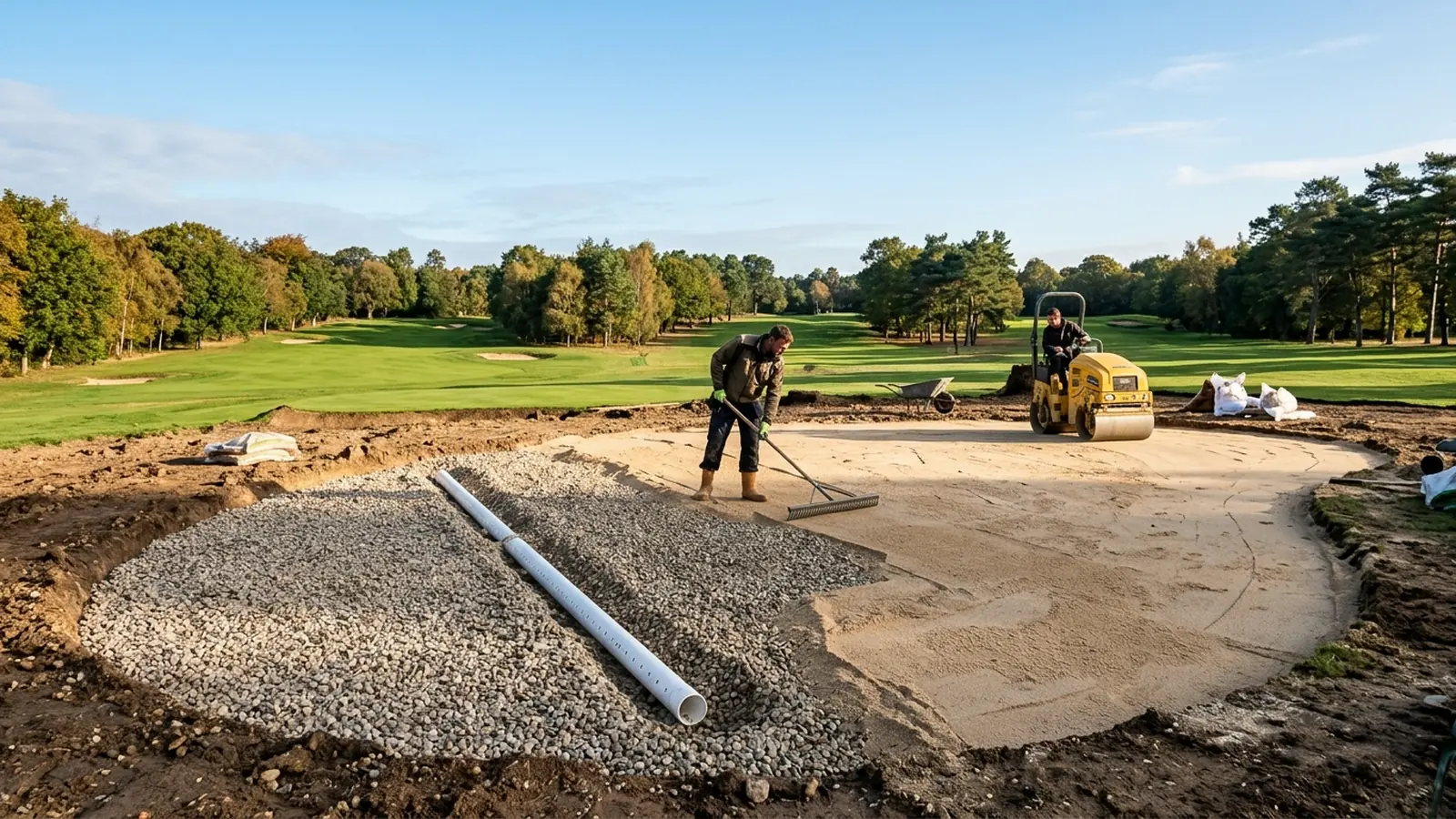
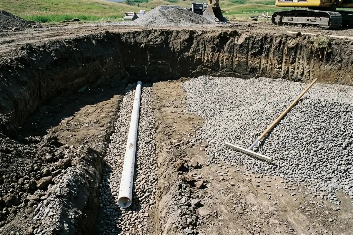
Subsurface collector trenches and pipe materials follow strict dimensional and aggregate-durability requirements across the cavity floor. Lateral drainage pipes should be spaced not more than 15 feet (5 meters) apart and have a continuous slope of 0.5 percent or greater to the main drain. Drainage pipe shall be perforated polyvinyl chloride (PVC) or corrugated polyethylene (PE) pipe conforming to ASTM D2729 or ASTM F667 with a minimum diameter of 4 inches (100 mm), while waffle drains, drain panels or any piping encased in geotextile sleeves are not recommended. Drainage trenches shall be at least 6 inches (150 mm) wide, 8 inches (200 mm) deep and cut into thoroughly compacted subsoil so that the drainage pipes maintain a consistent 0.5-percent slope. A layer of gravel is placed in the drainage trenches to a minimum depth of 1 inch (25 mm), and may be deeper than 1 inch to ensure that when the drainage pipes are installed they have a continuous slope of at least 0.5 percent. As an alternative to round pipe in a trench, flat pipe conforming to ASTM D7001 may be placed directly on the prepared subgrade, and the flat pipe should be a minimum of 12 inches (300 mm) wide and should not be covered with a geotextile sleeve. The entire subgrade is covered with clean, washed crushed stone or pea gravel to a minimum thickness of 4 inches (100 mm), and the surface of the finished gravel layer should be 12 inches (300 mm) below the finished grade (14 to 16 inches or 350 to 400 mm if an intermediate layer is required) and shall conform to the proposed finished grade, plus or minus 1 inch. Questionable gravel materials should be tested for stability using the Micro-Deval test ASTM D6928, and a loss of material greater than 18 percent using this method is unacceptable.
Gravel Blanket Bridging, Permeability Factors, and the Intermediate Layer
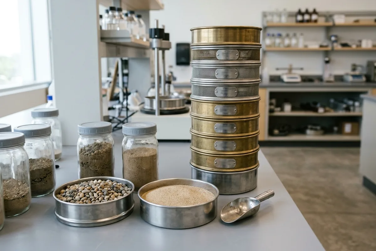
Omitting the coarse-sand intermediate choker layer in a two-tier USGA green depends on mechanical particle arching at the interface between the rootzone sand and the underlying gravel blanket. As a general guideline for a two-tier profile, select gravel with a particle size diameter between 2 mm and 9.5 mm. The bridging factor is calculated by dividing the D15 of the gravel (the particle size diameter below which 15 percent of gravel particles by weight are smaller) by the D85 of the rootzone (the particle size diameter below which 85 percent of rootzone particles by weight are smaller), and if the bridging factor is less than or equal to 8, the rootzone and gravel can be used in combination without an intermediate layer. USGA Table 1 specifies a Bridging Factor D15 (gravel) / D85 (rootzone) ≤ 8, a Permeability Factor D15 (gravel) / D15 (rootzone) ≥ 5, and a Uniformity Factor D90 (gravel) / D15 (gravel) ≤ 3 when the intermediate layer is not required. Under USGA Table 1, gravel Uniformity Factors also specify 100% passing a 12-mm screen, ≤ 10% passing a 2-mm screen, and ≤ 5% passing a 1-mm screen.
Reconciling Legacy and Revised Two-Tier Bridging Factors with Three-Tier Choker Layers
Agronomy specifications and laboratory compatibility reports distinguish between the earlier two-tier bridging multiplier, the updated two-tier threshold, and the three-tier intermediate layer option. Under the 1993 USGA specification, the smallest 15% of the gravel particles must have diameters no more than 5 times greater than the largest 15% of the root zone particles in a 2-tier USGA profile. In the April 1994 USGA revised specifications, two-tier gravel without a choker layer specified a Bridging factor D15 (gravel) ≤ 5 x D85 (rootzone), a Permeability factor D15 (gravel) ≥ 5 x D15 (rootzone), and Uniformity D90 (gravel) / D15 (gravel) ≤ 2.5. In Thomas Turf Services Certificate 0743.01 tested under ASTM Methods F1632 and C136-01, 3/8” Gravel (D15 = 2.88, D90 = 8.44, Uniformity = 2.9 ≤ 3) paired with #55 Bunker Sand (D15 = 0.23, D85 = 0.82) achieved a Bridging Factor of 3.5 (≤ 8) and a Permeability Factor of 12.4 (≥ 5). When an intermediate layer is required, spread the intermediate layer to a uniform thickness of 2 to 4 inches (50 to 100 mm) over the gravel layer—for example, if a 3-inch depth (75mm) is selected, the material shall be spread to a consistent 3-inch depth. Under USGA Table 2, when the intermediate layer is used, the gravel layer recommendation is ≤ 10% larger than 0.5 inch (12.7 mm), ≥ 65% between 0.250 inch (6.4 mm) and 0.375 inch (9.5 mm), and ≤ 10% smaller than 2 mm, while the intermediate layer recommendation is ≥ 90% between 1 mm and 4 mm.
| Compatibility Criterion | Legacy USGA Two-Tier Specification | Current USGA Two-Tier and Laboratory Example |
|---|---|---|
| Bridging Factor, Permeability Factor, and Gravel Uniformity | In the April 1994 USGA revised specifications, two-tier gravel without a choker layer specified a Bridging factor D15 (gravel) ≤ 5 x D85 (rootzone), a Permeability factor D15 (gravel) ≥ 5 x D15 (rootzone), and Uniformity D90 (gravel) / D15 (gravel) ≤ 2.5. | USGA Table 1 specifies a Bridging Factor D15 (gravel) / D85 (rootzone) ≤ 8, a Permeability Factor D15 (gravel) / D15 (rootzone) ≥ 5, and a Uniformity Factor D90 (gravel) / D15 (gravel) ≤ 3 when the intermediate layer is not required. |
| Gravel Sieve Cutoffs and Laboratory Compatibility Verification | Under the 1993 USGA specification, the smallest 15% of the gravel particles must have diameters no more than 5 times greater than the largest 15% of the root zone particles in a 2-tier USGA profile. | Under USGA Table 1, gravel Uniformity Factors also specify 100% passing a 12-mm screen, ≤ 10% passing a 2-mm screen, and ≤ 5% passing a 1-mm screen. In Thomas Turf Services Certificate 0743.01 tested under ASTM Methods F1632 and C136-01, 3/8” Gravel (D15 = 2.88, D90 = 8.44, Uniformity = 2.9 ≤ 3) paired with #55 Bunker Sand (D15 = 0.23, D85 = 0.82) achieved a Bridging Factor of 3.5 (≤ 8) and a Permeability Factor of 12.4 (≥ 5). |
USGA Rootzone Particle Size, Physical Properties, Amendments, and Quality Control
Rootzone mixtures must balance particle size gradation, organic or inorganic amendment stability, and laboratory physical performance before and during bulk blending. In USGA putting green rootzones, sand is defined as any particle between 0.05 and 2 mm in diameter, and quartz sands that are predominately silicon dioxide (SiO2) are chemically inert and resistant to chemical decomposition. If soil is used in the rootzone mixture, it shall preferably be a screened, 0.5-inch (12.5 mm) sandy loam soil having a minimum sand content of 60 percent and a clay content of 5 to 20 percent. USGA Table 3 recommended particle size distribution for a putting green rootzone mixture specifies 0% coarse gravel (above 4 mm, No. 5 sieve), ≤ 3% fine gravel (2.0 – 3.4 mm, No. 10 sieve), and ≤ 10% combined in the fine gravel and very coarse sand (1 – 2 mm, No. 18 sieve) range. USGA Table 3 specifies ≥ 60% of the rootzone particles by weight in the combined coarse sand (0.5 – 1.0 mm, No. 35 sieve) and medium sand (0.25 – 0.5 mm, No. 60 sieve) range. USGA Table 3 specifies rootzone fine sand (0.15 – 0.25 mm, No. 100 sieve) at ≤ 20%, very fine sand (0.05 – 0.15 mm, No. 270 sieve) at ≤ 5%, silt (0.002 – 0.05 mm) at ≤ 5%, clay (below 0.002 mm) at ≤ 3%, and total fines (very fine sand + silt + clay) at ≤ 10% combined. USGA Table 3 specifies a Coefficient of Uniformity (D60/D10) of 1.8 - 3.5 for rootzone mixtures with peat, 2.0 - 3.5 for rootzone mixtures with inorganic amendments, and 2.0 - 3.5 for pure sand rootzone mixtures.
Peat, Compost, Physical Property Testing, and Construction Quality Control Intervals
Amendment selection and stockpile quality control testing govern moisture retention and pore stability across the finished rootzone. The peat used in a USGA rootzone mixture shall have an organic matter content of at least 85 percent by weight as determined by loss on ignition ASTM D2974, Method C, and the peat shall be screened to no larger than 0.25 inches (6.4 mm). USGA Tips for Success Table 2 compares Sphagnum peat (pH 4-4.5, organic matter (%) 90 - 98, water holding capacity (%) 700 - 1,400, density 7 - 9 lbs./cu. ft., yield 3-5 lbs. OM/cu.ft.) with Reed sedge peat (pH 4.5-7, organic matter (%) 85- 90, water holding capacity (%) 400 - 500, density 14 - 16 lbs./cu. ft., yield 6 - 10 lbs. OM/cu.ft.). Any compost selected for a USGA rootzone mixture amendment shall have 95 – 100% passing a 0.25-inch screen (6.4 mm), organic matter content ≥ 50% as determined by ASTM D2974, moisture content between 30% – 60%, carbon to nitrogen ratio between 15:1 – 30:1, Solvita Compost Maturity Index of 7 – 8, electrical conductivity ≤ 6 dS/m, and pH between 4 – 8. A USGA rootzone mixture shall have physical properties tested per ASTM F1815 meeting the Table 4 recommended ranges of Total Porosity 35%–55%, Air-filled Porosity 15%–30%, Capillary Porosity 15%–25%, and Saturated Hydraulic Conductivity (Ksat) ≥ 6 inches/hour (150 mm/hr.). For quality control testing during production, it is recommended that gravel be tested every 500 tons, that rootzone mixture should be tested to determine at least particle size and organic matter every 500 to 1,000 tons, and that full performance testing be repeated on the first 200 tons of rootzone mixture if the baseline mixture was tested several weeks or months earlier. USGA Table 5 confidence intervals for quality control testing specify 50% on fine gravel and very coarse sand, 15% on coarse sand, medium sand, and fine sand, 30% on very fine sand, 10% on total porosity, 15% on air-filled porosity and capillary porosity, 25% on saturated hydraulic conductivity, and ± 0.2 for mixes above 1% OM or ± 0.15 for mixes with ≤ 1% OM. The USGA rootzone mixture should be spread and uniformly firmed to a 12-inch (300 mm) depth with a tolerance of plus or minus 1 inch (25 mm). Variable-depth putting green rootzone construction (studied from 1998 through 2002) involves decreasing the rootzone depth to 8 to 10 inches in elevated areas and increasing the rootzone depth to 14 to 16 inches in low-lying areas. USGA Appendix 1 lists ASTM C136 for sieve analysis of fine and coarse aggregates, ASTM D75 for sampling aggregates, ASTM D854 and ASTM D5550 for specific gravity, ASTM F1815 for physical properties, ASTM F1632 for particle size analysis and sand shape grading, and ASTM F1647 for organic matter content of rootzone mixes. Adjacent greenside bunker specifications require golf course bunker sand particle size (0.25–1.0 mm ≥ 65%, silt and clay ≤ 3%), above 2.4 kg/cm2 penetrometer firmness, bunker liner blankets, and 4-inch herringbone bunker drainage. Detail on bunker sand testing and underdrain isolation is covered in our guide to bunker sand particle size and drainage.
| Sieve Fraction | USGA Rootzone Gradation | UC Davis Fine-Sand Gradation |
|---|---|---|
| Gravel and Very Coarse Sand | USGA Table 3 recommended particle size distribution for a putting green rootzone mixture specifies 0% coarse gravel (above 4 mm, No. 5 sieve), ≤ 3% fine gravel (2.0 – 3.4 mm, No. 10 sieve), and ≤ 10% combined in the fine gravel and very coarse sand (1 – 2 mm, No. 18 sieve) range. | UC Davis Table 1 fine-sand green specifications list 0% above 2.00 mm, 0-10% between 1.00 and 2.00 mm, 60%+ medium sand between 0.250 and 0.500 mm, and 2-8% silt and clay. |
| Primary Sand Fraction and Fines | USGA Table 3 specifies ≥ 60% of the rootzone particles by weight in the combined coarse sand (0.5 – 1.0 mm, No. 35 sieve) and medium sand (0.25 – 0.5 mm, No. 60 sieve) range. USGA Table 3 specifies rootzone fine sand (0.15 – 0.25 mm, No. 100 sieve) at ≤ 20%, very fine sand (0.05 – 0.15 mm, No. 270 sieve) at ≤ 5%, silt (0.002 – 0.05 mm) at ≤ 5%, clay (below 0.002 mm) at ≤ 3%, and total fines (very fine sand + silt + clay) at ≤ 10% combined. | The University of California method specifies an unamended sand in which 90 to 100 percent of the particles are no larger than 1 mm in diameter and no finer than 0.1 mm, with the dominant fraction between 0.5 mm and 0.25 mm. In UC Davis fine-sand green tests, a sand bed with medium sand (0.50 to 0.25 mm) that should be 60 percent or more is placed 12 inches deep and retains 1.25 to 1.50 inches of water in the surface 4 inches after gravitational drainage. |
California Method Pure-Sand Profile, Vadose Hydrology, and Black Layer Diagnostics
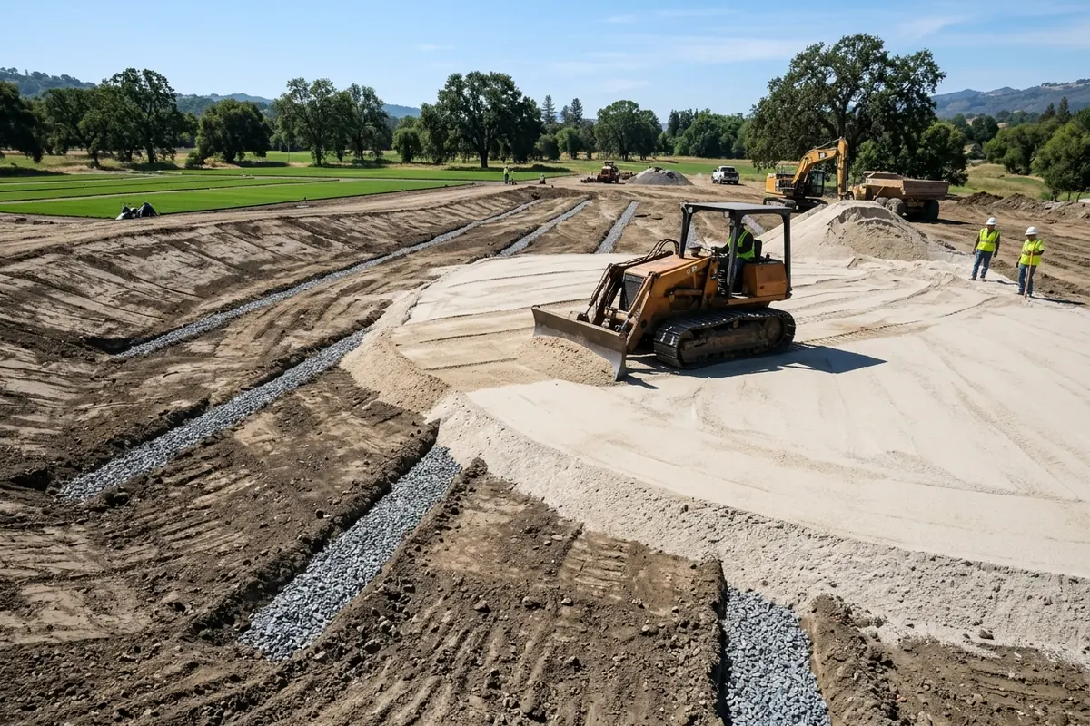
The University of California putting green construction method omits the continuous gravel blanket and relies on a narrower sand size envelope placed directly over a sloped, trenched subbase. In a California green, drainage gravel (1/4-inch diameter pea gravel) is only placed in the trench and is not used as a drainage blanket, and a layer of gravel equal to the pipe diameter should cover the crown of the pipe. In the California method, unamended sand is firmed to a uniform 12-inch depth, and selective placement of 1 to 2 cubic yards of sand for surface contouring may be as much as 3 inches thicker (for a total depth of 15 inches). Trenchless California greens use 12-inch wide panel drainage pipe (about 1-inch thick) laid flat on the subgrade, where a 1-inch loss of grade can pond water and some preliminary calculations suggest that flow velocities in a panel pipe laid flat would fall below the 1.5 foot per second minimum for self cleaning. Most University of California greens are graded evenly at the subbase so that they have a 2 to 4 percent slope from back to front, and surface contours do not change the total depth of sand at the highest point more than 3 inches (7.5 cm). The University of California method specifies an unamended sand in which 90 to 100 percent of the particles are no larger than 1 mm in diameter and no finer than 0.1 mm, with the dominant fraction between 0.5 mm and 0.25 mm. UC Davis Table 1 fine-sand green specifications list 0% above 2.00 mm, 0-10% between 1.00 and 2.00 mm, 60%+ medium sand between 0.250 and 0.500 mm, and 2-8% silt and clay. In UC Davis fine-sand green tests, a sand bed with medium sand (0.50 to 0.25 mm) that should be 60 percent or more is placed 12 inches deep and retains 1.25 to 1.50 inches of water in the surface 4 inches after gravitational drainage. In the University of California pure-sand green method, fine unamended sand retains moisture to carry turf for 2 to 3 days between irrigations while draining excess water from the surface root zone in less than 15 minutes. In the University of California review, at most construction sites the parent soil has a very low water infiltration rate of less than an inch (2.5-cm) per hour, whereas the infiltration rate of sand can vary from 10 to 50 inches (25 cm to 125 cm) or more per hour when compacted with a soil-kneading compactor in the laboratory.
Perched Water Table Mechanics, Flow Path Direction, and Black Layer Biogeochemistry
At field capacity in a USGA putting green, a perched water table forms at the base of the root zone, and optimally this zone of saturated soil should extend no more than about 6 inches up from the interface. In a California green with a root zone thickness of 12 inches and a drain line spacing of, say, 18 feet, much of the path length for water flow is directed laterally, whereas in a USGA green all flow paths across the root zone are vertical. Saturated hydraulic conductivity of a root zone mix for a USGA green ranges from 6 to 24 inches per hour (from the 1993 revision), whereas the conductivity of a California green can range from 20 to 60 inches per hour. In Ohio State University Table 4-1, design subsurface drainage coefficients are 1 inch per day for push-up greens and tees, 1 inch per hour for high-sand tees (6 - 8 inch root zone), 2 inches per hour for high-sand greens (California and USGA), and 4 inches per hour for sand bunkers. In USGA specification putting greens, black layer is a layer of metal sulphide formed from hydrogen sulphide (H2S) gas that is produced from sulphur reducing bacteria (SRB), and the reaction of the H2S with available minerals. Matching sprinkler precipitation rates and distribution uniformity to rootzone infiltration—using the audit steps in golf course irrigation pressure and uniformity—helps prevent surface waterlogging. For related turf and course infrastructure guides, return to sports facilities.
Sources
- United States Golf Association (USGA) — USGA Recommendations for a Method of Putting Green Construction
- United States Golf Association (USGA) — Building the USGA Putting Green: Tips for Success
- Ohio State University (Dr. Ed McCoy) — Drainage Systems for Golf Courses: Drainage of Greens, Tees and Sand Bunkers
- University of California Cooperative Extension (M. Ali Harivandi) — Golf Green Construction: A Review of the University of California Method
- University of California, Davis (William B. Davis) — Sands and Their Place on the Golf Course: The Fine Sand Green
- University of Arizona Cooperative Extension (David M. Kopec) — Revised Specifications for United States Golf Association Greens Construction
- Thomas Turf Services, Inc. — Geotechnical Putting Green Materials Compatibility Testing Report
- Pitchcare Agronomy Consultancy (Colin Mumford) — Black Layer in USGA Specification Constructed Putting Greens