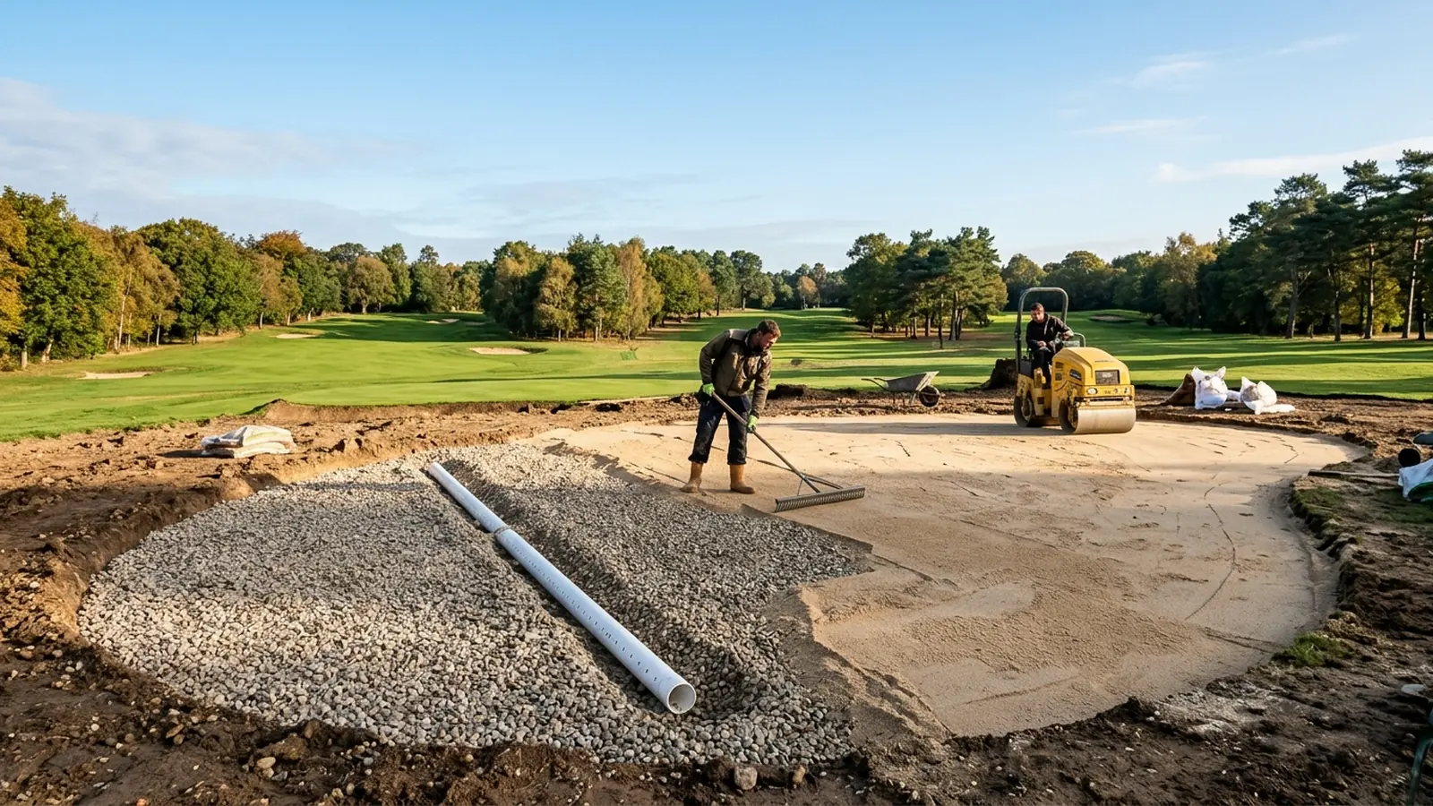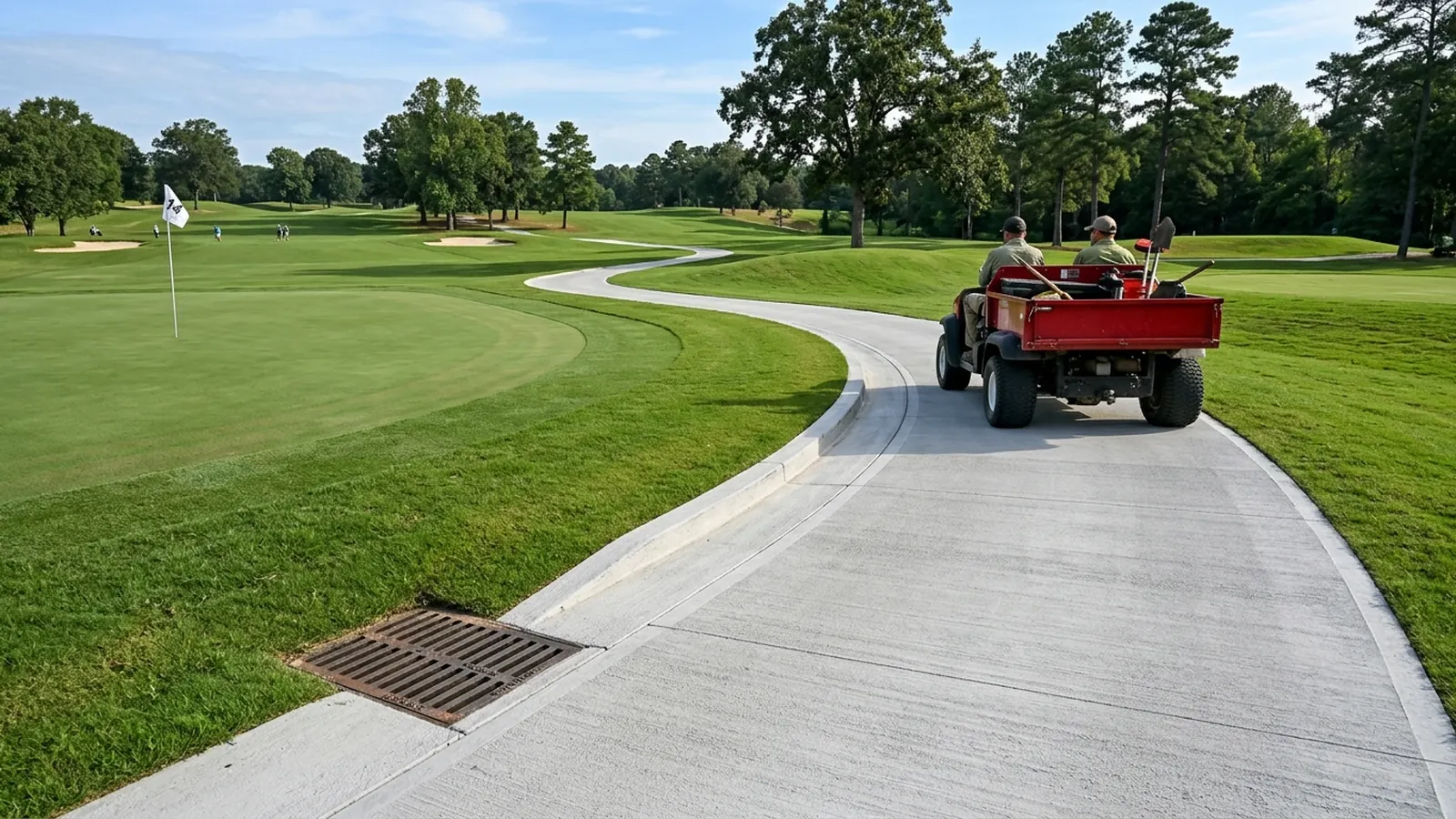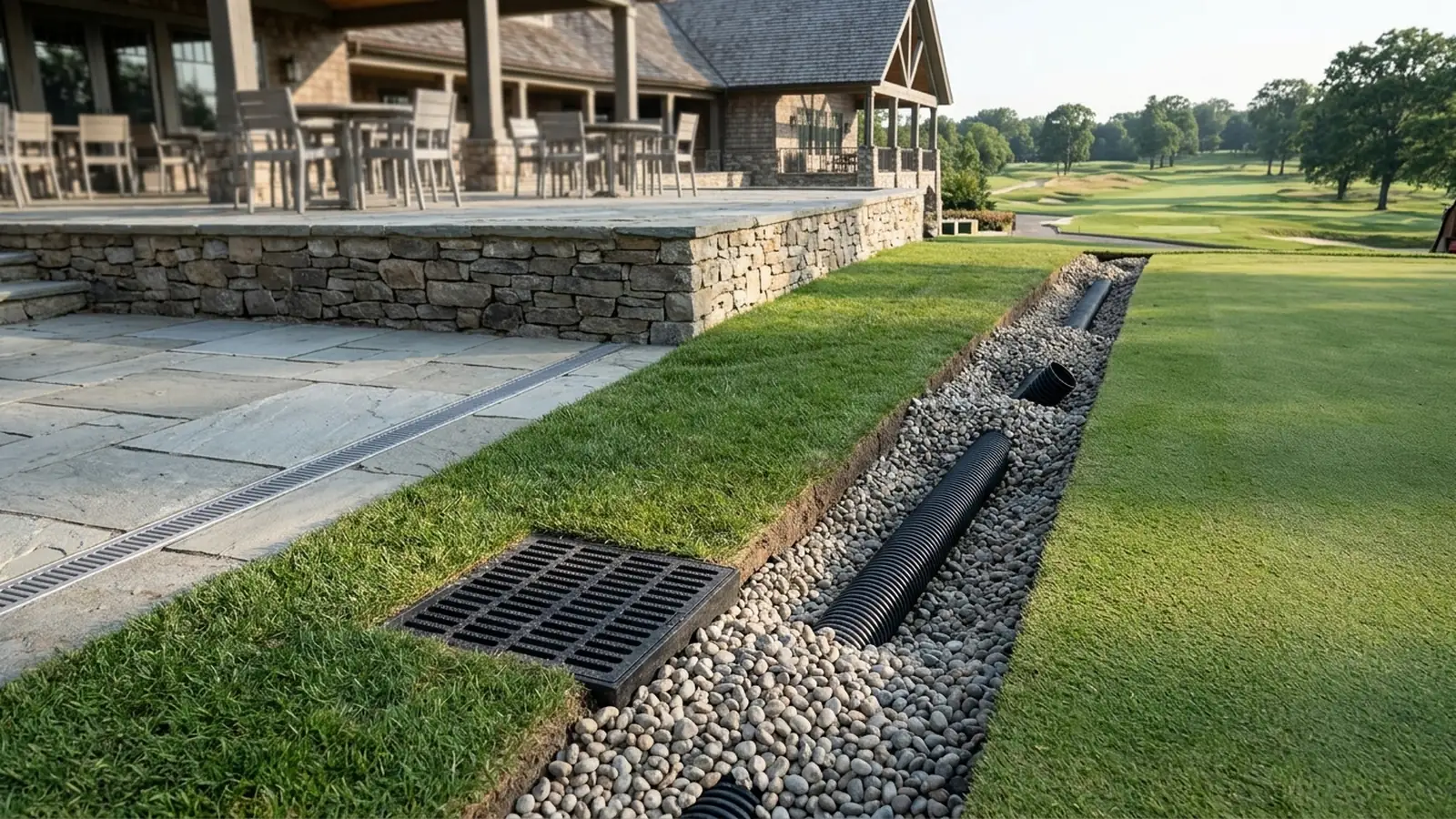
Coordinating golf course drainage across fairways, putting green surrounds, and the clubhouse terrace boundary prevents upslope turf runoff and subsurface interflow from overwhelming building hardscape drains. Surface drainage is the controlled removal of excess surface water flowing across the surface or ponded in depressions, while subsurface drainage is the removal of excess subsurface water that has infiltrated into the soil and created waterlogged soil conditions. In agricultural production, water ponding on the soil surface and water-saturated soil conditions can be tolerated for up to several days without a significant yield loss, whereas in recreational turf situations the intensity attributes of both surface and subsurface drainage are emphasized because return-to-play speed and soil resistance to traffic compaction are critical. In Golf Inc. (Donna Campbell, September 16, 2026), Tim Christman of Barringer Construction defines the critical ‘seam’ where horizontal golf course construction meets the vertical construction of buildings and structures, noting that poor coordination among golf course architects, civil engineers, and building contractors where those scopes meet creates drainage and elevation problems. Related site infrastructure guides are organized in our sports facilities engineering archive, alongside clubhouse terrace and patio drainage systems, putting green construction profiles, bunker sand particle size and drainage, and golf course irrigation pressure and uniformity.
Side-by-Side Engineering Boundary: Course-Side Turf Drainage vs Clubhouse Patio Drainage
Separating course-side turf hydrology from building plaza plumbing clarifies where agricultural and sportsturf collector mains terminate and where architectural trench drains take over.
| Engineering Parameter | Golf Course Fairway and Surrounds Drainage | Clubhouse Patio and Terrace Drainage |
|---|---|---|
| Runoff Coefficient and Hydrologic Formula | Rational Method `q = C i A` (cfs, acres, in./hr); OSU Table 2-1 turf `C` spans `0.10–0.40` on `0–5%` slopes, `0.16–0.55` on `5–10%` slopes, and `0.22–0.60` on `10–30%` slopes from open sandy loam to tight clay. | IPC Section 1106 flow `Q (GPM) = 0.0104 × C × i × A` with `C = 0.95–1.00` (OSU Table 2-2 pavement/impervious `0.83–1.00`) over deck area plus `50%` of abutting walls (`5,200 sq ft` effective terrace → `216.15–351.24 GPM` into a `6-in.` `760 GPM` header). |
| Inlet Geometry and Surface Interception | `4–6 in.` pea-gravel French/blind-inlet trenches in steep roughs; `<= 2 in.` coarse-sand slit arrays spaced `3–4 ft` across fairways (including `1-in.` oval-pipe Cambridge slits) and grated low-spot catch basins. | ADA heel-proof `<= 1/4–5/16 in. (6.0–8.0 mm)` Type 316 wedge-wire (`5–6 mm` slots) or `8.0 mm` frameless porcelain-joint slot drains with removable sediment baskets every `15–20 ft (4.5–6.0 m)`. |
| Pipe Materials and Corrosion Environment | Smooth-interior clay, concrete, or dual-wall HDPE (`ADS N-12`, Manning's `n = 0.012`) vs single-wall corrugated tubing (`n = 0.018`, requiring larger diameter for equal capacity). | Pickled and passivated Type 316 stainless (`UNS S31600`, `2%–3% Mo`) required within `20 ft` of turf chelated-iron, sulfate/potash fertilizers, and chloride de-icers that pit Type 304 within `12–24 months`. |
Surface vs Subsurface Golf Course Drainage and Rational Method Hydrology
Soil pore distribution, regulatory wetland boundaries, and watershed concentration time govern how rainfall partitions between overland sheet flow and subsurface percolation across a golf course. High sand content soils with a large proportion of macropores have permeabilities ranging from 1 to 100 in/hr, whereas heavy textured clay soils containing predominantly micropores may have permeabilities as low as 0.01 in/day. In a soil with a permeability of 1 in/hr, gravity drainage causes the water table to fall two feet over the course of a day, whereas in a clay soil with a permeability of 0.01 in/day the water table falls only 0.01 inches in a day. One inch of rain on one acre of golf course turf equals 22,610 gallons. Section 404 of the Clean Water Act regulates the discharge of dredged or fill material in wetlands, streams, and rivers under permits issued by the Army Corps of Engineers; while maintaining existing drainage systems is allowed, it is not permissible to increase the effectiveness of existing drainage systems within wetlands or drain/fill non-exempt wetlands without a Section 404 permit.
Rational Method Runoff Coefficients and Watershed Time of Concentration
Evaluating peak overland discharge across undulating turf and adjacent hardscape surfaces relies on the Rational Method and watershed travel time. The Rational Method calculates peak surface runoff rate as q = C i A, where q is peak runoff rate in cubic feet per second (cfs), C is the dimensionless runoff coefficient (ranging from 0.0 for no runoff to 1.0 when all rain yields runoff on an impervious surface), i is expected rainfall intensity in inches per hour for a given return period, and A is watershed area in acres. In OSU Table 2-1, rural watershed runoff coefficients (C) for pasture/turf on flat (0-5% slope) terrain are 0.10 for open sandy loam, 0.30 for silt and clay loam, and 0.40 for tight clay; on rolling (5-10% slope) terrain are 0.16, 0.36, and 0.55; and on hilly (10-30% slope) terrain are 0.22, 0.42, and 0.60. In OSU Table 2-2, urban and hardscape runoff coefficients (C) are 0.18 for parks, 0.28 for playgrounds, 0.40 for single-family residential areas, 0.83 for pavement and downtown business areas, and 1.00 for 100% impervious surfaces. Watershed time of concentration (tc, in minutes) is given by tc = 0.0078 L0.77 S-0.385, where L is watershed length from discharge to the most remote point in feet and S is watershed slope in feet per feet; when calculated tc is less than 8 minutes, 8 minutes is used as a reasonable minimum storm duration estimate. In OSU Table 2-3 for small watersheds, a 300 ft watershed length has a time of concentration of 4 minutes at slope 1.0, 3 minutes at slope 2.0, and 2 minutes at slope 4.0 to 10.0; a 1,000 ft length has a time of concentration of 9 minutes at slope 1.0, 7 minutes at slope 2.0, and 6 minutes at slope 4.0; and a 2,000 ft length has 16 minutes at slope 1.0 and 12 minutes at slope 2.0. In the OSU worked Rational Method calculation for a 25-year rainstorm on a 16-acre wooded watershed on predominately silt loam soil with a 2,000-foot maximum flow length and 2.0% (0.02 ft/ft) average slope, the time of concentration is 12 minutes, the adjusted rainfall intensity is 6.8 inches per hour (8.5 in/hr St. Louis base multiplied by the 0.8 regional isoline), and C = 0.3, yielding a peak runoff rate Q of 32.6 cubic feet per second (0.3 x 6.8 x 16).
Grassed Channels, Catch Basins, Orifice Flow Control, and Fairway Slit Drains
Surface water that does not infiltrate into the turf rootzone is routed through grassed parabolic swales, hillside diversions, grated catch basins, or narrow sand-filled interceptor slits. For parabolic grass-lined golf course channels, the minimum practical width at a 1-foot depth is W = 10 feet (with 10:1 bottom-quarter, 5:1 second-quarter, and 3:1 top-half side slopes), and adding a 0.3-foot freeboard at a 3:1 slope increases the top width from 10 feet to 11.8 feet (rounded to 12 feet). Published permissible water flow velocities for grass-lined channels range from 3 to 8 feet per second (fps) depending on grass species, channel bed soil, and channel slope; using 3 fps as a conservative design limit, any channel where peak runoff velocity exceeds 3 fps risks channel erosion and requires lining with riprap, concrete, or asphalt. When a grass-lined hillside diversion is excavated upslope to protect a fairway from hillside runoff, a 20-foot-wide strip above the diversion should also be maintained in turf to prevent suspended sediment from being deposited in and silting up the diversion bed. USGA Green Section stormwater management guidelines recommend using grass swales (biofilters) with gentle grades of 1 to 2% where possible to allow maximum filtration before runoff enters water bodies, and eliminating any situations where grass clippings, motor oil, pesticides, or fertilizers drain directly to catch basins or storm drains.
Catch Basin Pipe Sizing, Slope Corrections, and Orifice Discharge Equations
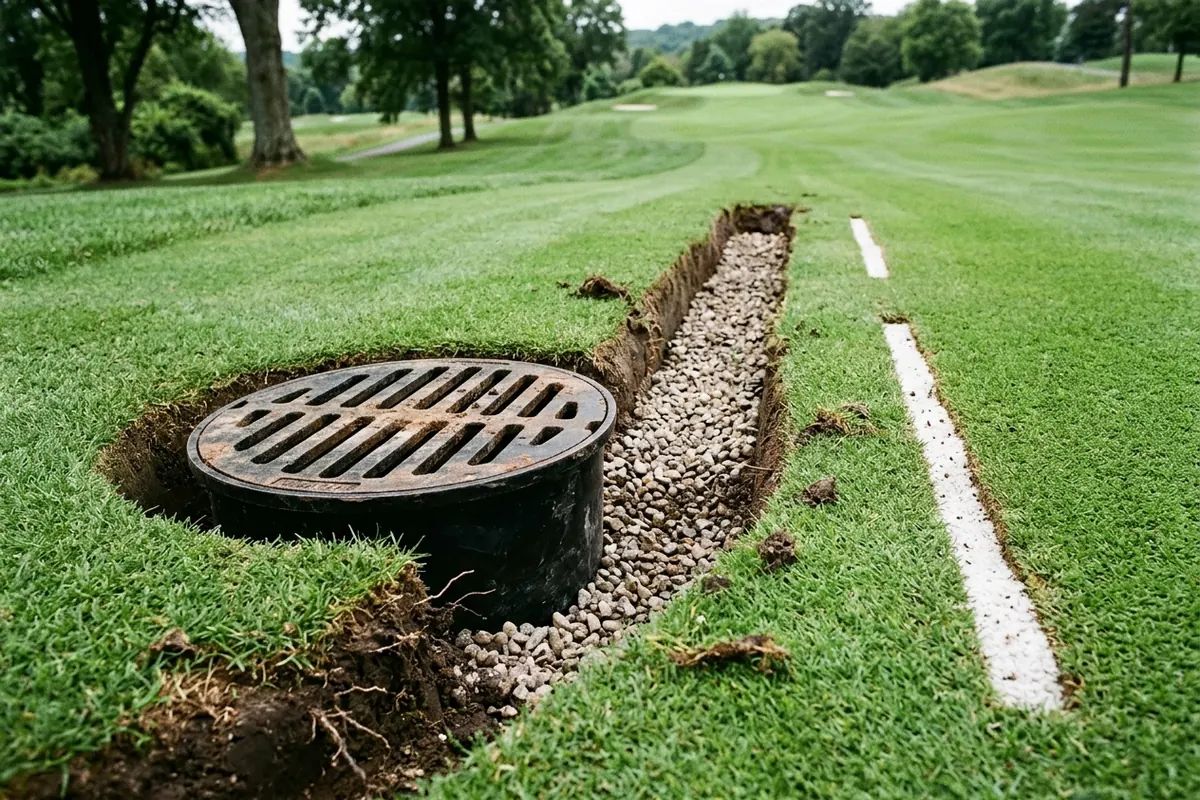
Localized depressions in fairways and roughs require properly supported risers, sediment traps, and horizontal outlet pipes matched to regional rainfall factors and grate opening areas. A surface inlet (open inlet or catch basin) removes surface runoff from localized fairway or greens-complex depressions via a vertical riser and flush removable grate; because bending horizontal flexible pipe 90 degrees toward the surface risks folding or pinching the pipe, a prefabricated elbow, end-capped tee, or junction box/drain basin (where downstream pipe diameter increases) should be installed. At Mayfield Country Club, surface risers with grates in low spots were installed using a double tee or cross clay pipe in the line so the basin below the flow line serves as a sediment trap that can be cleaned out periodically, and drain ditches were checked with an 8-foot wooden ditching frame built 3/16 inch out of parallel to verify a minimum grade of 2.34 inches of fall in 100 feet. Under OSU Table 2-7 (corrugated drain pipe at 0.5% slope, tight clay C = 0.6, and a 50-year, 8-minute rainstorm across regional adjustment factors 0.6 for northern Michigan, 1.0 for eastern Missouri at 12 inches per hour, and 1.4 for south Florida), a 4-inch horizontal catch basin pipe drains 980 sq ft (35 ft diameter), 590 sq ft (27 ft), or 420 sq ft (23 ft), and a 6-inch pipe (0.29 cfs capacity) drains 2890 sq ft (61 ft), 1740 sq ft (47 ft), or 1240 sq ft (40 ft). Under OSU Table 2-7 (corrugated drain pipe at 0.5% slope, C = 0.6, and a 50-year, 8-minute duration rain intensity across regional adjustment factors 0.6, 1.0, and 1.4), an 8-inch pipe drains 6220 sq ft (89 ft circular diameter), 3730 sq ft (69 ft), or 2670 sq ft (58 ft); a 10-inch pipe drains 11000 sq ft (120 ft), 6780 sq ft (93 ft), or 4840 sq ft (79 ft); and a 12-inch pipe drains 18000 sq ft (150 ft), 11000 sq ft (120 ft), or 7860 sq ft (100 ft). Under OSU Table 2-7 (for regional rain intensity adjustment factors of 0.6, 1.0, and 1.4), collector mains connecting multiple surface inlets drain up to: 33000, 20000, or 14000 sq ft for a 15-inch pipe; 54000, 32000, or 23000 sq ft for an 18-inch pipe; 82000, 49000, or 35000 sq ft for a 21-inch pipe; and 116000, 70000, or 50000 sq ft for a 24-inch pipe. Under OSU Table 2-8, when the minimum slope along a horizontal catch basin pipe exceeds 0.5%, the Table 2-7 pipe diameter can be corrected downward: a 6-inch pipe reduces to 4 inches at slopes greater than 3%; an 8-inch pipe reduces to 6 inches at slopes > 2.5% (or 4 inches at > 16%); a 10-inch pipe reduces to 8 inches at > 2% (or 6 inches at > 8%); a 12-inch pipe reduces to 8 inches at > 4.5% (or 6 inches at > 24%); and a 15-inch pipe reduces to 8 inches at > 17%. Under OSU Table 2-9, at 1.0 ft water head a 2-inch orifice discharges 48 gpm, a 3-inch orifice 108 gpm, a 4-inch orifice 192 gpm, a 5-inch orifice 300 gpm, and a 6-inch orifice 432 gpm; at 4.0 ft head they discharge 96, 216, 384, 600, and 864 gpm respectively (where 1 cubic foot per second equals 449 gallons per minute). A surface inlet grating acts as an orifice whose maximum discharge (in gpm) depends on the total area of the grate openings (A, in square inches) and the maximum height of water above the orifice (H, in feet); for an 8-inch diameter grate containing 4 slots measuring 5 inches long by 0.75 inches wide (15 square inches total area) and 6 inches of maximum allowed ponding height above the grate, maximum discharge through the grate is about 160 gpm.
French Drains, Sand Slit Arrays, and Secondary Fairway Interceptors
Where surface grading alone cannot clear slow-draining fairways, gravel French drains and closely spaced sand slits bypass the native topsoil and feed underlying lateral pipes. In OSU Chapter 2, French drains used as surface runoff interceptors are 4- to 6-inch-wide trenches backfilled with pea gravel (best used as a single line in roughs on short, steep slopes, and termed a blind inlet when containing a perforated pipe in the trench bottom), whereas slit drains are up to 2 inches wide, backfilled with coarse sand, and placed as an array with spacing of 3 to 4 feet in finer, shorter-mowed fairway turf (including the Cambridge System with a 1-inch-wide perforated oval pipe). When water movement along a French drain or slit drain trench is not assisted by a pipe in the trench (and the trench does not intersect a sandy/gravelly subsoil or the gravel envelope of a subsurface drain line), the trench grade must be greater than 2%, whereas placing a pipe in the trench allows grades down to 0.5%. In Shelton Sportsturf Drainage primary fairway specifications, the main drain is installed along the side of the fairway (avoiding central herringbone upheaval) with laterals spaced at 5, 7, or 10 metres apart running across the fairway; main drains are typically 100 mm pipe in a 118 mm trench, and laterals are 60 mm pipe in a 78 mm trench or 80 mm pipe in a 97 mm trench. In Shelton Sportsturf Drainage specifications, sand slitting (slit trench drainage) consists of 50 mm wide trenches spaced 1 to 2 metres (1,000 mm to 2,000 mm) apart and 250 mm deep, backfilled with 150 mm of gravel and topped off with 100 mm (2 inches) of free-draining coarse sand. In Shelton Sportsturf Drainage Appendix 1 comparing secondary golf course drainage systems, Gravel Band Drainage uses a 25 mm wide by 300 mm deep trench at 400 mm to 1,000 mm spacing (cost 1x, output circa 6,000 m/day); System 25 uses a 25 mm wide by 350 mm deep trench at 400 mm to 1,000 mm spacing (cost 2x, output circa 3,000 m/day); Slit Trench Drainage (sand slitting) uses a 50 mm wide by 250 mm deep trench at 1,000 mm to 2,000 mm spacing with aggregate brought up to 2 inches of the surface and topped with free-draining sand (cost 3x, output circa 3,000 m/day); and Lightening-Drain uses a 35 mm wide by 450 mm deep trench at 500 mm to 1,000 mm spacing (cost 4-5x, output circa 1,500-2,000 m/day). The TopDrain one-pass sand slit drainage machine trenches two sand drain lines per pass, removes the excavated soil from each trench without touching the turf, and backfills clean sand directly into trenches that are two inches wide.
Subsurface Fairway Drainage and Manning’s Equation Collector Mains
Subsurface fairway drainage systems rely on open-channel gravity hydraulics, self-cleaning pipe velocities, and washed aggregate envelopes to lower perched water tables without pressurizing the collector network. Smooth-walled drainage pipe (Manning’s n = 0.012, including clay, concrete, or corrugated plastic with a smooth-walled insert such as ADS N-12) has higher flow capacity than corrugated pipe (Manning’s n = 0.018), which requires a larger pipe diameter due to the hydraulic roughness introduced by internal corrugations. Per OSU Table 2-4 (ADS Technical Notes 2.109, Mannings n = 0.012), smooth-walled 4-inch, 6-inch, and 8-inch drainage pipes carry: for 4-inch pipe, 0.15 cfs at slope 0.5, 0.21 cfs at slope 1.0, and 0.29 cfs at slope 2.0; for 6-inch pipe, 0.43 cfs at slope 0.5, 0.61 cfs at slope 1.0, and 0.86 cfs at slope 2.0; and for 8-inch pipe, 0.93 cfs at slope 0.5, 1.31 cfs at slope 1.0, and 1.85 cfs at slope 2.0. Per OSU Table 2-4 (Mannings n = 0.012), smooth-walled 10-inch, 12-inch, 15-inch, 18-inch, and 24-inch collector mains carry: for 10-inch pipe, 1.68 cfs (slope 0.5), 2.37 cfs (slope 1.0), and 3.36 cfs (slope 2.0); for 12-inch pipe, 2.73 cfs (0.5), 3.86 cfs (1.0), and 5.46 cfs (2.0); for 15-inch pipe, 4.95 cfs (0.5), 7.00 cfs (1.0), and 9.90 cfs (2.0); for 18-inch pipe, 8.05 cfs (0.5), 11.4 cfs (1.0), and 16.1 cfs (2.0); and for 24-inch pipe, 17.3 cfs (0.5), 24.5 cfs (1.0), and 34.7 cfs (2.0). Per OSU Table 2-5 (ADS Technical Notes 2.109, Mannings n = 0.018), single-wall corrugated 4-inch, 6-inch, and 8-inch drainage pipes carry: for 4-inch pipe, 0.10 cfs at slope 0.5, 0.14 cfs at slope 1.0, and 0.19 cfs at slope 2.0; for 6-inch pipe, 0.29 cfs at slope 0.5, 0.41 cfs at slope 1.0, and 0.57 cfs at slope 2.0; and for 8-inch pipe, 0.62 cfs at slope 0.5, 0.87 cfs at slope 1.0, and 1.23 cfs at slope 2.0. Per OSU Table 2-5 (Mannings n = 0.018), corrugated 10-inch, 12-inch, 15-inch, 18-inch, and 24-inch collector pipes carry: for 10-inch pipe, 1.12 cfs (slope 0.5), 1.58 cfs (slope 1.0), and 2.24 cfs (slope 2.0); for 12-inch pipe, 1.82 cfs (0.5), 2.57 cfs (1.0), and 3.64 cfs (2.0); for 15-inch pipe, 3.30 cfs (0.5), 4.67 cfs (1.0), and 6.60 cfs (2.0); for 18-inch pipe, 5.36 cfs (0.5), 7.59 cfs (1.0), and 10.7 cfs (2.0); and for 24-inch pipe, 11.6 cfs (0.5), 16.3 cfs (1.0), and 23.1 cfs (2.0).
| Diameter Tier | Smooth-Walled Pipe Capacity | Single-Wall Corrugated Pipe Capacity |
|---|---|---|
| Laterals and Sub-Mains (`4"`, `6"`, `8"`) | `n = 0.012` (`0.5% / 1.0% / 2.0%` slope): `4"` = `0.15 / 0.21 / 0.29 cfs`; `6"` = `0.43 / 0.61 / 0.86 cfs`; `8"` = `0.93 / 1.31 / 1.85 cfs` | `n = 0.018` (`0.5% / 1.0% / 2.0%` slope): `4"` = `0.10 / 0.14 / 0.19 cfs`; `6"` = `0.29 / 0.41 / 0.57 cfs`; `8"` = `0.62 / 0.87 / 1.23 cfs` |
| Fairway Collector Mains (`10"`–`24"`) | `n = 0.012`: `10"` = `1.68 / 2.37 / 3.36 cfs`; `12"` = `2.73 / 3.86 / 5.46 cfs`; `15"` = `4.95 / 7.00 / 9.90 cfs`; `18"` = `8.05 / 11.4 / 16.1 cfs`; `24"` = `17.3 / 24.5 / 34.7 cfs` | `n = 0.018`: `10"` = `1.12 / 1.58 / 2.24 cfs`; `12"` = `1.82 / 2.57 / 3.64 cfs`; `15"` = `3.30 / 4.67 / 6.60 cfs`; `18"` = `5.36 / 7.59 / 10.7 cfs`; `24"` = `11.6 / 16.3 / 23.1 cfs` |
Trench Depth, Gravel Envelopes, Self-Cleaning Velocity, and Geotextile Clogging
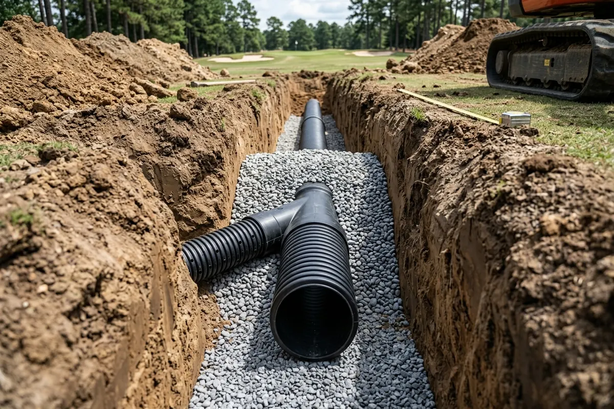
Trench invert depth, sand or gravel envelope gradation, and open-channel grade selection prevent pipe crushing, silt sedimentation, and anaerobic filter-fabric blinding. In composite fairway subsurface drainage systems (gridiron for uniform one-way slopes or herringbone for central swales), main lines follow natural valleys or run perpendicular to contours, while laterals are laid across the slope with a gentle downward grade of 0.5 to 2.0% to intercept subsurface throughflow (interflow). To prevent pipe crushing from heavy wheeled traffic, minimum soil cover over clay and concrete drain pipe is 2 feet, while minimum cover for corrugated plastic pipe embedded in a gravel envelope ranges from 12 inches (ADS Product Note 3.116) to 2 feet (ASTM D 2321-89); for golf course drainage intensity, recommended fairway drain line depths range from 2 to 2.5 feet to trench bottom (invert) with spacing from 30 feet on high-permeability soils down to 15 feet on low-permeability soils. For USGA fairway subsurface drainage projects, standard drain line depth is 24 inches (with lines installed as shallow as 18 inches where soil, machinery, or rock dictate), lateral spacing ranges from 10 to 25 feet depending on budget and severity, and trench widths of 5 to 7 inches are backfilled with coarse sand percolating 30 to 80 inches per hour rather than native soil. For subsurface drain pipes in an aggregate envelope, ASTM D 2321-89 recommends a minimum of 4 inches of aggregate below the pipe, 6 inches above the pipe, and 8 inches on either side of the pipe (whereas less conservative golf course practice uses a minimum of 2 inches surrounding the pipe and 4 inches over the crown), with aggregate particle diameters no greater than 1/6 of the pipe diameter and capped with a minimum of 6 inches of topsoil. Corrugated plastic drainage tubing is manufactured in continuous coils of 500 feet for 2-inch diameter pipe and 240 feet for 4-inch diameter pipe, and in 20-foot lengths for diameters larger than 6 inches; panel drains (edge or fin drains such as ADS AdvanEDGE) measure 1 to 2 inches thick and 4 to 18 inches wide and install vertically in a 4-inch overall trench thickness (or 3 to 6 inches plus product thickness under proposed ASTM methods). Geotextile filter fabrics wrapped around drainage pipes or trenches are not generally recommended in golf course drainage because fine sand and silt particles build up a flow-restricting filter cake on the fabric or anaerobic bacteria on the external wet side produce a slimy biofouling capsule that plugs the fabric pores. Subsurface drain lines are designed to function as gravity open channels with an air-water interface throughout the pipe; when an undersized or overloaded pipe fills to capacity and becomes pressurized, water escaping through the inlet holes liquefies and erodes the surrounding trench soil (eroding the pipe out of its trench near steep outlets) or creates a pressurized subsurface water lens that floats the turf and thatch layer off the soil surface. In OSU Table 3-2, subsurface drainage coefficients for humid-region golf course fairways and roughs (when surface water is excluded) are 1/2 to 1-1/2 inches per day (mid-value 1.0 inch per day) for low-permeability silt or clay loam to loam soils, and 1-1/2 to 2-1/2 inches per day for high-permeability sandy clay loam to sandy loam soils; at a 1.0 inch per day drainage coefficient, a 2-acre low-permeability fairway discharges 37.8 gallons per minute (gpm). Subsurface drainage pipe grades should be selected to develop a minimum flow velocity of at least 1.4 feet per second (with 1.5 feet per second recommended for greens and tees, and 3 feet per second achieved in a 6-inch smooth-walled pipe flowing full at 1% slope, equivalent to 60 yards per minute or 1 mile in half an hour) so that the pipe is self-cleaning and flushes sediment during larger flow events. In the OSU Figure 3-4 gridiron fairway drainage design example (4 corrugated plastic laterals spaced 20 feet apart, each 650 feet long = 13,000 sq ft or 0.3 acres per lateral, 1.2 acres total, at 1.5% slope and 2 inches per day drainage coefficient), each lateral discharges 11 gpm at ~1.5 ft/s (2-inch minimum pipe), the second and third main sections require a 3-inch minimum pipe (0.6 acres at ~1.75 ft/s), and the fourth main section conveying all 1.2 acres (44 gpm) requires a 4-inch minimum pipe at just under 2 ft/s, with capped surface wyes placed where main grades flatten for inspection and flushing. In ATE Drainage flat-pipe specifications for golf courses, FLATTEX is an HDPE flat drain with a thin 4 cm profile and 17 cm width, an SN25 mechanical compression resistance rating, and a 450-micron fabric sleeve. In Turf Drainage Co. of America (TDA) bunker and seepage drainage specifications, Turf Drain waffle seepage pipe is stated to have 45 times the collection space of 4″ perforated pipe per linear foot. In ADS Golf and Turf Drainage specifications, engineered golf course drainage components include N-12 Dual Wall Pipe, Singlewall corrugated pipe, Nylopast Drains & Basins, Duraslot trench drains, turf flow pipe, StormTech Chambers, and Inserta Tee lateral connections, with traditional putting green layouts using 4” (100 mm) perforated laterals and 6” (150 mm) solid N-12 pipe or ASTM D7001 flat pipe >= 12” (300 mm) in width without a geotextile sleeve.
Where the Clubhouse Patio Drain Takes Over: Perimeter Cutoffs at the Seam
At the perimeter where the closing hole and practice green approach the clubhouse terrace, hillside seepage cutoffs and solid-pipe transitions isolate course water before building plumbing codes and architectural slot drains govern the deck. Hillside seepage interceptors are placed across a hillside nearly perpendicular to the slope at the intersection of a steep slope and a flatter slope to intercept lateral subsurface water flowing over a clay subsoil, fragipan, or cemented layer before it emerges as a seep; test holes dug 2 to 3 feet deep upslope locate where the water table is 1 to 2 feet below the surface, and the interceptor trench is dug to approximately 2.5 feet deep and backfilled with gravel at least to the water table depth (or fitted with a vertically placed 12-inch panel drain). Under OSU Table 3-3, hillside interceptor inflow rates (in gpm per 1000 ft of trench) are 65 to 450 gpm/1000 ft for coarse sand and gravel, 30 to 110 gpm/1000 ft for sandy loam, 20 to 40 gpm/1000 ft for silt loam, and 10 to 100 gpm/1000 ft for clay and clay loam, with required inflow rates increased by 10% for slopes of 2 to 5%, by 20% for slopes of 5 to 12%, and by 30% for slopes greater than 12%. In OSU Table 4-1, subsurface drainage coefficients are 1 in/day for native-soil push-up greens and tees, 1 in/hr for high-sand tees (6- to 8-inch root zone), 2 in/hr for high-sand putting greens (both California and USGA profiles, where USGA saturated conductivity ranges from 6 to 24 inches per hour and California conductivity ranges from 20 to 60 inches per hour), and 4 in/hr for sand bunkers. In the OSU Chapter 4 high-sand putting green drainage example (7400 sq ft green at 1% subgrade slope, 2 inches per hour drainage coefficient, 14 corrugated plastic laterals spaced 15 feet apart at 30 degrees yielding 0.5% lateral slope, longest lateral 60 feet draining 900 sq ft), a uniform 8-inch trench depth yields just over 1 foot per second in a 4-inch lateral (below the 1.5 feet per second self-cleaning target), whereas deepening the lateral trench from 8 inches to 15.2 inches at the main yields a 1.5% self-cleaning slope, and the main requires a 6-inch corrugated pipe (or 5-inch smooth-walled pipe) flowing at about 2.5 feet per second. In the USGA Recommendations for a Method of Putting Green Construction, subsurface drainage pipe shall be perforated PVC (ASTM D2729) or corrugated PE (ASTM F667) with a minimum diameter of 4 inches (100 mm) in trenches at least 6 inches (150 mm) wide and 8 inches (200 mm) deep on >= 1 inch (25 mm) of gravel at >= 0.5% continuous slope spaced not more than 15 feet (5 meters) apart, or ASTM D7001 flat pipe >= 12 inches (300 mm) wide on the subgrade; geotextile fabric must never cover pipes or trenches, and a perimeter drain must be placed along the cavity wall at any low point where a main drain exits the green. Per USGA Building the USGA Putting Green: Tips for Success (Tips 11–14), a capped cleanout port on the high side and an inspection port riser on the low side should be installed; bunker drains must be kept separate from putting green drains or connected only downstream of the low-side inspection port; and wherever a drainage pipe exits a putting green cavity into a soil trench, it must transition from slotted/perforated pipe to solid, non-perforated pipe so the line does not become clogged or create a constantly wet area along the drainage line. Rootzone layering for adjacent putting greens is detailed in putting green construction profiles, while bunker floor lines are covered in bunker sand particle size and drainage.
Clubhouse Terrace Plumbing Codes, Grate Load Classes, and Outfall Structures
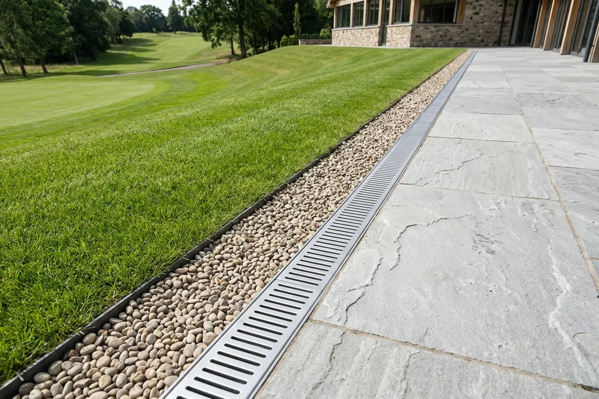
Once drainage crosses from the turf perimeter cutoff onto the clubhouse hardscape or discharges to course outfalls, plaza storm plumbing rules, pedestrian heel-proof slot limits, stainless steel alloy selection, and receiving basin designs apply. Under the International Plumbing Code (IPC Tables 1106.2 and 1106.3), building roof and plaza/terrace storm drains are sized in four steps using the 100-year, 1-hour rainfall rate (IPC Appendix B) applied to the square feet of horizontal area served by each drain plus half of the area of any vertical walls that divert rain onto the deck, with IPC Section 101.5 prohibiting any reduction in pipe size in the direction of flow. On the clubhouse patio side of the drainage boundary, stormwater flow rate in GPM is calculated under IPC Section 1106 as (C × i × effective area) / 96.23 = 0.0104 × C × i × effective area (with C = 0.95 to 1.00 for waterproofed plaza decks plus 50% of abutting vertical walls per IPC Section 1106.4; e.g., a 4,000 sq ft terrace abutting a 2,400 sq ft wall has an effective catchment area of 5,200 sq ft, generating 216.15 GPM at i = 4.0 in./hr and 351.24 GPM at 6.5 in./hr, drained into a 6 in. main header rated at 760 GPM at 1/4 in./ft slope per IPC Table 1106.2). Under ASME A112.6.3 / CSA B79.3 (referenced by trench drain standard ASME A112.6.8 / CSA B79.8) and DIN EN 1433, drain load classifications are: Light Duty (LD) up to 441 lb (200 kg) / DIN EN 1433 Load Class A up to 3,372 lb (15 kN); Medium Duty (MD) up to 1,984 lb (900 kg) / Load Class B up to 28,101 lb (125 kN); Heavy Duty (HD) up to 3,638 lb (1,650 kg) / Load Class C up to 56,202 lb (250 kN); Extra Heavy Duty (XHD) up to 7,500 lb (3,402 kg) / Load Class D up to 89,923 lb (400 kN); and Special Duty (SD) up to 10,000 lb (4,536 kg) / Load Class E up to 134,885 lb (600 kN) and Load Class F up to 202,328 lb (900 kN). Under ADA Grating Guidelines and Heel-Proof Design criteria (Slot Drain Systems), walkway gratings must have slots positioned perpendicular to the main direction of travel with a maximum slot width of ½ inch (13 mm), while a heel-proof drain grate designed to prevent debris accumulation and protect high heels features slots or perforations smaller than 0.313 inches (8 mm). Per DuraTrench ADA trench drain specifications, an ADA-compliant trench drain grate cannot have openings greater than 1/2 inch perpendicular to the predominant direction of travel, and the pavement or ground around an ADA-compliant trench drain grate shall not have a slope greater than 1:48 (approximately a 2% slope or 1/4 inch per foot, with 3/16 inch per foot recommended). Clubhouse terrace drainage hardware specifies <= 1/4 in. to 5/16 in. (6.0 to 8.0 mm) heel-proof openings using either Type 316 stainless steel wedge-wire (T-Bar) grates with 5 to 6 mm (3/16 to 1/4 in.) slot widths or frameless architectural slot drains with an 8.0 mm (5/16 in.) throat opening set inside a 600 x 600 mm porcelain paver joint line with removable sediment strainer baskets at 15 to 20 ft (4.5 to 6.0 m) intervals. Because golf course superintendents apply liquid chelated iron (ferric/ferrous sulfate), ammonium sulfate, potassium chloride (muriate of potash) turf fertilizers, and chloride winter de-icing salts within 20 feet of the clubhouse terrace, standard Type 304 stainless steel (18% Cr, 8% Ni, 0% Mo) suffers chloride pitting and brown tea-staining within 12 to 24 months, requiring pickled and passivated Type 316 stainless steel (UNS S31600, 16%–18% Cr, 10%–14% Ni, 2.0%–3.0% Molybdenum). A classical gravity drainage outlet uses a 10- to 15-foot terminal section of non-perforated metal pipe connected to the drainage pipe by a concrete collar, discharging at least one foot above the normal water level in the receiving waterway, and protected by riprap whenever design outlet flow velocity exceeds 3 feet per second. For an isolated 1600 sq ft silt loam tee (C = 0.3) generating 160 cubic feet of runoff from a 10-year, 24-hour storm, a 10 by 10 foot aggregate-filled dry well (40% aggregate porosity) must be 4 feet deep (a 400 cubic foot excavation), whereas a horizontal pipe subsurface reservoir (ADS Technical Note 2.120, minimum 2 feet soil cover) requires 22.6 feet of 36-inch pipe or 50.9 feet of 24-inch pipe. Constructed golf course stormwater wetlands (OSU Chapter 5) include extended detention wetlands (requiring >= 10 acres of contributing watershed and cleanout every 2 to 5 years) and pocket wetlands (requiring 1 to 10 acres of watershed and cleanout every 10 years); both require a minimum wetland-to-watershed area ratio of 0.1 (e.g., 1 acre wetland for a 10-acre watershed), a forebay and micropool excavated 1 to 6 feet below normal pool level, a low marsh (6 to 18 inches deep) and high marsh (0 to 6 inches deep), and outflow control via either a reverse-slope pipe within 1 foot of normal pool level or a 6-inch perforated Hickenbottom inlet riser along its upper 2- to 4-foot length paired with a stoplog weir. Pedestal paver plenums and bi-fold door sill pans on the building side of the boundary are detailed in clubhouse terrace and patio drainage systems, and additional turf infrastructure references are available in sports facilities.
Sources
- Ohio State University (Dr. Ed McCoy) — Drainage Systems for Golf Courses
- United States Golf Association (USGA) — Recommendations for a Method of Putting Green Construction (2018 Revision)
- United States Golf Association (USGA) — Building the USGA Putting Green: Tips for Success (2018 Revision)
- USGA Green Section Record (Nancy P. Sadlon, Nov/Dec 1992) — Concern for Surface Runoff
- USGA Green Section Record (Charles H. Tadge, March/April 1980) — Drainage Is Important to Turfgrass Management
- USGA Green Section Record (Patrick O’Brien, Sept/Oct 2005) — Planning a Golf Course Drainage Project
- Shelton Sportsturf Drainage — A Guide to Sportsturf Drainage Techniques for Golf Courses
- Hummer Turfgrass Systems — Specialized Maintenance Support for Golf Courses
- ATE Drainage — Golf course drainage: an essential application for high-performance, sustainable courses
- Turf Drainage Co. of America — Application Areas
- Advanced Drainage Systems (ADS) — Golf and Turf Drainage Brochure
- Golf Inc. Magazine (Donna Campbell, Sept 16, 2026) — Building a smarter golf course starts below the ground
- C1S Group MEP Engineering — Four Steps to Sizing Roof Drains (IPC Section 1106)
- Slot Drain Systems — Load Class Ratings, ADA Grating & Heel-Proof Design
- DuraTrench Linear Drainage Engineering — ADA Compliant Trench Drain