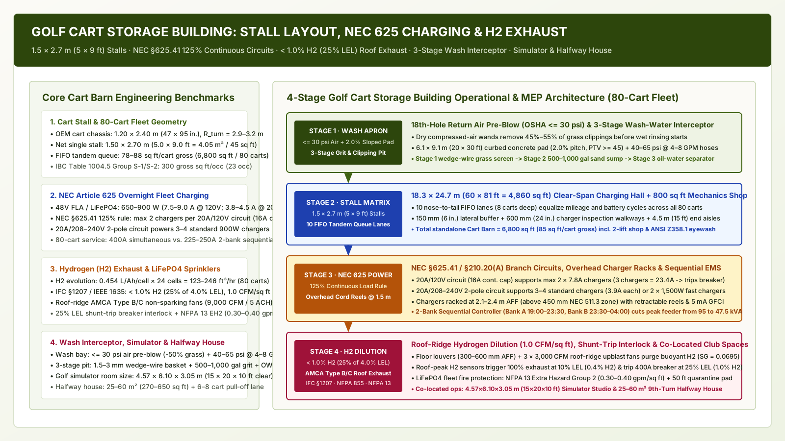
Golf course fleet operations fail when architects size a golf cart storage building (Cart Barn) using passenger-car parking ratios, wire three battery chargers onto a single 20A / 120V branch circuit, or vent returning wash water into a standard 4 in. floor drain. Within the first tournament season, under-sized aisles trap attendants in morning shotgun gridlock, overloaded thermal-magnetic breakers trip 30 minutes after night lockup to leave 16 to 24 carts dead on the 1st tee, unventilated roof truss pockets accumulate explosive > 4.0% hydrogen gas (H2) plumes during flooded lead-acid equalization, and buoyant grass clippings mat inside drain elbows to ferment into foul hydrogen sulfide (H2S) sewer gas.
Engineering a code-compliant, high-throughput golf cart storage building and its co-located club operations spaces requires coordinating five quantitative building systems:
- Cart Barn Stall Envelope (
1.5 m × 2.7 m/5.0 ft × 9.0 ft=45 sq ftNet) & FIFO Queue Topology: Accommodate standard1.20 m × 2.40 m(47 × 95 in.) Club Car Tempo, E-Z-GO RXV, and Yamaha Drive2 fleet carts (inside turning radius 2.90 to 3.20 m[9.5 to 10.5 ft]) inside1.50 m × 2.70 m(4.05 m²/45.0 sq ft) single parking stalls with150 mm(6 in.) lateral buffers,300 mm(12 in.) longitudinal bumper gaps, and600 mm(24 in.) charger inspection walkways every second lane. For an 80-cart 18-hole fleet, a 10-lane one-way First-In, First-Out (FIFO) nose-to-tail tandem queue requires a4,860 sq ft(451.5 m²,60 × 81 ft) clear-span charging hall and6,800 gross sq ft(631.7 m²,85.0 sq ft/cart) including the wash apron, 2-bay mechanics shop, and switchgear room (23 occupantsat300 gross sq ft/occupantunderIBC Table 1004.5 Group S-1/S-2). - NEC Article 625 Overnight Charging Circuits (
125%Continuous Load Rule) & Sequential Load Management: Size all fleet charging branch circuits and feeders at125%of continuous load (NEC §625.41,§625.42, and§210.20(A)), capping continuous draw at80%(16.0 A) of a20Acircuit breaker. Limit standard650 to 900 W(7.5 to 9.0 A@120V AC)48Vflooded lead-acid (FLA) andLiFePO4overnight chargers to maximum2 chargersper20A / 120Vcircuit (or 3 to 4 chargers per 20A / 208–240V 2-pole circuit, and1 charger per 20A / 120V circuitfor1,200–1,500 Wfast chargers), suspended from2.1 to 2.4 m(7 to 8 ft) AFF overhead Unistrut racks on spring-retractable#10/#12 AWG SOOWcord reels with5 mAClass A GFCI protection (NEC §625.54). Use a 2-bank sequential load controller (NEC §625.42(A)) to cut 80-cart peak charging demand from95.0 kVA(400A3-phase service) to47.5 kVA(225A–250Aservice). - Hydrogen (
H2) Electrolysis Dilution (< 1.0% H2=25% LEL) &NFPA 13 EH2Fire Sprinklers: Dilute the123.2 to 246.4 ft³/hr(2.05 to 4.11 CFM) of buoyant hydrogen gas (specific gravity 0.0695) evolved by 80 equalizing48Vlead-acid carts (0.454 L H2/Ah/cellacross24 cellsperIEEE 1635) below1.0%by volume (25%of the4.0%Lower Explosive Limit) using floor-level intake louvers (300–600 mmAFF) and roof-ridge upblast centrifugal exhaust fans (AMCA 99-0401 Type B/Cspark-resistant aluminum wheels,1.0 CFM/sq ft=4,860 to 9,000 CFM/5.0 ACHperIFC §1207andNFPA 1) interlocked with roof-peakH2sensors that trigger a24V DCmain-breaker shunt trip at25% LEL. Protect48V / 51.2V LiFePO4lithium-ion fleets with NFPA 13 Extra Hazard Group 2 (0.30 to 0.40 gpm/sq ftover2,500 sq ft) overhead fire sprinklers and an exterior50 ftsetback quarantine pad (NFPA 855). - Wash-Down Apron Hydraulics (
<= 30 psiAir Pre-Blow) & 3-Stage Grit/Clipping/Oil Interceptor: Pre-clean returning carts with OSHA<= 30 psi(29 CFR 1910.242(b)) dry compressed-air wands (cutting grass clippings entering the wet wash stream by 50%perGCM / GCSAA), rinse with40 to 65 psi@4 to 8 GPMlow-pressure hoses over a2.0%sloped concrete pad (wet PTV >= 45), and route effluent through a Stage 1 inclined1.5–3.0 mmType 316 stainless wedge-wire grass-clipping screen basket, a Stage 2500 to 1,000 galdual-chamber weir-baffled silica sand settling basin (20–30 minHRT), and a Stage 3API / EN 858-1coalescing oil-water separator (<= 10–15 mg/L) or85%–90%closed-loop biological water recycling skid. - Co-Located Club Operations — Commercial Golf Simulator Room Size (
15 × 20 × 10 ft) & 9th-Turn Halfway House (25–60 m²): Frame reclaimed bag-room or cart-barn teaching bays to a clear golf simulator room size of4.57 m W × 6.10 m D × 3.05 m H(15 × 20 × 10 ft=300 sq ft) for centered right/left-handed driver swings across camera (Foresight QuadMAX/Falcon,16–18 ftdepth) and radar (TrackMan 4,20 ftdepth) launch monitors. Out on the 9th/10th turn, replace muddy, weather-exposed huts with a25 to 60 m²(270 to 650 sq ft) golf course halfway house featuring a2.4–3.0 moverhang, aPTV >= 45drained concrete queue apron, and a6 to 8 cartparallel pull-off staging lane (ADA Chapter 10 §1006).
Within our club operations discipline, this engineering specification directly expands our foundational on-course inspection checklist selling drinks and balls from a point on the course—which identifies the four field failures at a simple course stop (sun and rain on stock, muddy standing pads, locked hatches during play hours, and unstaffed payment/spoilage handling)—into permanent civil, architectural, and MEP criteria for both the golf course halfway house and the central golf cart storage building. It also completes the back-of-house spatial program initiated in golf clubhouse design: arrival sequence, spike-proof circulation zones, and member-visitor flow (which maps the exterior bag drop, 600-bag high-density mobile storage room reclaiming 690 sq ft for a simulator studio, and 4-wave cart staging apron), pairs with the EN 1433 Class B125/C250 vehicular trench drain load ratings and 2.0% sloped aprons in patio drainage system for clubhouse terraces: pedestal pavers vs. sloped mortar and trench drains, contrasts with interior ASHRAE 62.1 (0.50 cfm/sq ft) negative-pressure shower exhaust in locker room design: negative-pressure ventilation, wet-zone separation, benches, and plinth lockers, and supports 144-player shotgun tournament cart staging in moving guests through a club on event day.
| Facility Subsystem | Governing Code / Standard | Design Benchmark (80-Cart 18-Hole Fleet) | Critical Sizing Formula / Threshold | Dominant Field Failure Mode Prevented |
|---|---|---|---|---|
| 1. Single Cart Stall & FIFO Barn Footprint | CED A03-005 · ADA §1006 · IBC Table 1004.5 (S-1/S-2) |
1.50 × 2.70 m (5.0 × 9.0 ft = 45 sq ft) stall; 6,800 sq ft (631.7 m²) gross barn (85 sq ft/cart) |
A_gross = (N × 45 sq ft × 1.35) + 600 + 800 + 540; 300 gross sq ft/occ (23 occ) |
Mirror/fender scraping on `1.2 × 2.4 m` carts; dead-end aisle gridlock; uneven fleet battery wear |
| 2. Overnight Fleet Charging Branch Circuits | NFPA 70 (NEC) Art. 625 (§625.41 / §625.42) & §210.20(A) |
Max 2 chargers per 20A/120V circuit (16A cap); 3–4 per 20A/208–240V circuit; overhead reels @ 1.5 m AFF |
I_breaker >= 1.25 × I_cont; 400A simultaneous vs. 225–250A 2-Bank Sequential EMS |
3 chargers (`23.4A`) tripping `20A` breakers at night; crushed floor cords; `5 mA` wet-floor shock (`NEC §625.54`) |
| 3. Roof-Ridge Hydrogen Exhaust & Fire Sprinklers | IFC §1207 · IEEE 1635 · NFPA 855 · NFPA 13 EH2 |
< 1.0% H2 (25% of 4.0% LEL); 1.0 CFM/sq ft (4,860–9,000 CFM / 5 ACH); AMCA Type B/C fans |
CFM = G_ft3_hr / (0.01 × 60) × 5; 25% LEL shunt-trip; NFPA 13 EH2 0.30–0.40 gpm/sq ft |
Roof-truss `H2` pocket ignition (`0.017 mJ` spark); cascading `LiFePO4` thermal runaway across parked rows |
| 4. Cart Wash-Down Apron & 3-Stage Interceptor | GCM / GCSAA · OSHA 1910.242(b) · EN 1433 B125 · EN 858-1 |
<= 30 psi dry air pre-blow + 6.1 × 9.1 m pad (2.0% slope, PTV >= 45) + 40–65 psi @ 4–8 GPM hoses |
Stage 1: 1.5–3 mm wedge-wire basket; Stage 2: 500–1,000 gal sand sump; Stage 3: OWS / 85% recycle |
Buoyant grass blades matting in pipes (`H2S` rotten-egg odor); silica bunker sand packing sewer lines |
| 5. Golf Simulator Room Size & Halfway House | Foresight · TrackMan · ADA Ch. 10 §1006 & §904.4 · UK HSE |
Simulator: 4.57 × 6.10 × 3.05 m (15 × 20 × 10 ft); Halfway House: 25–60 m² + 6–8 cart pull-off lane |
Ceiling >= 3.05 m (10 ft); queue pad PTV >= 45 @ 2.0% pitch; >= 48 in. (1.22 m) cart passage |
Tall-golfer driver ceiling strikes; radar blind spots; muddy halfway-house queues & blocked cart paths |
1. Golf Cart Storage Building (Cart Barn) Stall Dimensions, Aisle Widths, and 72-to-100-Cart Fleet Layouts
Key takeaway: Standardize every single parking stall in a golf cart storage building at 1.50 m × 2.70 m (5.0 ft × 9.0 ft = 4.05 m² / 45.0 sq ft net stall area) with a 600 mm (24 in.) charger inspection walkway between paired rows, select one-way nose-to-tail FIFO tandem queue lanes (78 to 88 sq ft/cart gross) for club-leased tournament fleets (or 45°/60° herringbone bays with a 3.6–4.2 m [12–14 ft] one-way aisle for random-access member carts), and budget 6,800 gross sq ft (631.7 m²) for a standalone 80-cart facility under IBC Table 1004.5 Group S-1/S-2 (300 gross sq ft/occupant).
OEM Golf Car Chassis Envelope and the 1.5 m × 2.7 m (5.0 × 9.0 ft) Single Stall Standard
Sizing a golf cart storage building around guesswork or compact automobile stalls (2.4 × 4.8 m / 8 × 16 ft) wastes structural steel span, while squeezing carts onto 1.25 m (4.1 ft) centerlines shears off side mirrors, scrapes body panels, and traps attendants between bumpers with nowhere to route charging leads. Across North American and European golf operations, all three dominant commercial 2-passenger fleet platforms—Club Car Tempo / Onward, E-Z-GO RXV / TXT, and Yamaha Drive2 Fleet—share a tightly standardized chassis envelope documented in CED Engineering Course A03-005 (An Introduction to Golf Clubhouse Design) and the U.S. Access Board ADA Chapter 10 Guide (§1006 Golf Car Passages and Shelters):
- Overall Vehicle Length (
Front Bumper to Rear Bag Hoop):2.39 to 2.44 m(94.0 to 96.0 in./7.83 to 8.00 ft) for standard 2-passenger fleet carts (stretching to 3.00–3.20 m [118–126 in. / 9.8–10.5 ft] for 4-passenger concierge/shuttle carts and 3.35–3.66 m [11.0–12.0 ft] for 6-passenger hospitality and beverage carts). - Overall Vehicle Width (
Rub-Rail to Rub-Rail):1.19 to 1.22 m(47.0 to 48.0 in./3.92 to 4.00 ft). - Overall Sun-Canopy Height:
1.74 to 1.83 m(68.5 to 72.0 in./5.71 to 6.00 ft) (rising to 1.95 m [77 in.] on lifted utility turf beds). - Wheelbase and Minimum Inside Turning Radius: Wheelbase of
1.66 to 1.68 m(65.5 to 66.1 in.) with a minimum inside turning radius of2.90 to 3.20 m(9.5 to 10.5 ft), requiring a5.80 to 6.40 m(19.0 to 21.0 ft) curb-to-curb180°turning circle. - Curb Weight by Battery Chemistry (
Trojan Battery& OEM Specs):430 to 520 kg(950 to 1,150 lb) when equipped with six8Vor four12Vflooded lead-acid (FLA) deep-cycle batteries (battery bank weight alone = 165 to 195 kg[360 to 430 lb]), dropping by20%to340 to 400 kg(750 to 880 lb) when equipped with a48V / 51.2VLithium Iron Phosphate (LiFePO4) pack (battery pack weight = 32 to 48 kg[70 to 105 lb]).
To provide safe door-to-fender operating tolerances around this 1.20 m × 2.40 m (4.0 × 8.0 ft) vehicle footprint, country club structural and civil specifications enforce a net single golf cart parking stall module of 1.50 m × 2.70 m (5.0 ft × 9.0 ft = 4.05 m² / 45.0 sq ft) (complementing the federal 1.52 × 2.44 m [60 in. × 96 in.] minimum unobstructed space inside on-course weather shelters mandated by ADA Chapter 10 §1006.3):
- Lateral Stall Pitch (
1.50 m/5.0 ftCenter-to-Center vs.1.20 m/4.0 ftCart Width): Leaves150 mm(6.0 in.) of lateral buffer on each side of the cart, creating a300 mm(12.0 in.) clear separation strip between adjacent parallel lanes when carts are parked along painted wheel stripes. Because attendants must walk between columns every evening to plug in DC charging leads, check electrolyte sight glasses, and connect single-point battery watering hoses, group tandem lanes in pairs (3.0 m[10.0 ft] double-row width) separated every second lane by a dedicated600 mm(24.0 in.) clear charger inspection and bag-handling walkway (yielding an effective lateral pitch of 1.65 m [5.5 ft] per row). - Longitudinal Stall Module (
2.70 m/9.0 ftPitch vs.2.40 m/8.0 ftCart Length): Provides300 mm(12.0 in.) of nose-to-tail bumper clearance between parked carts in a tandem queue. That300 mmlongitudinal gap allows staff to step laterally between bumpers to reach rear-fender charge receptacles or unstrap golf bags from the rear bag well without rolling an entire column of eight carts forward.
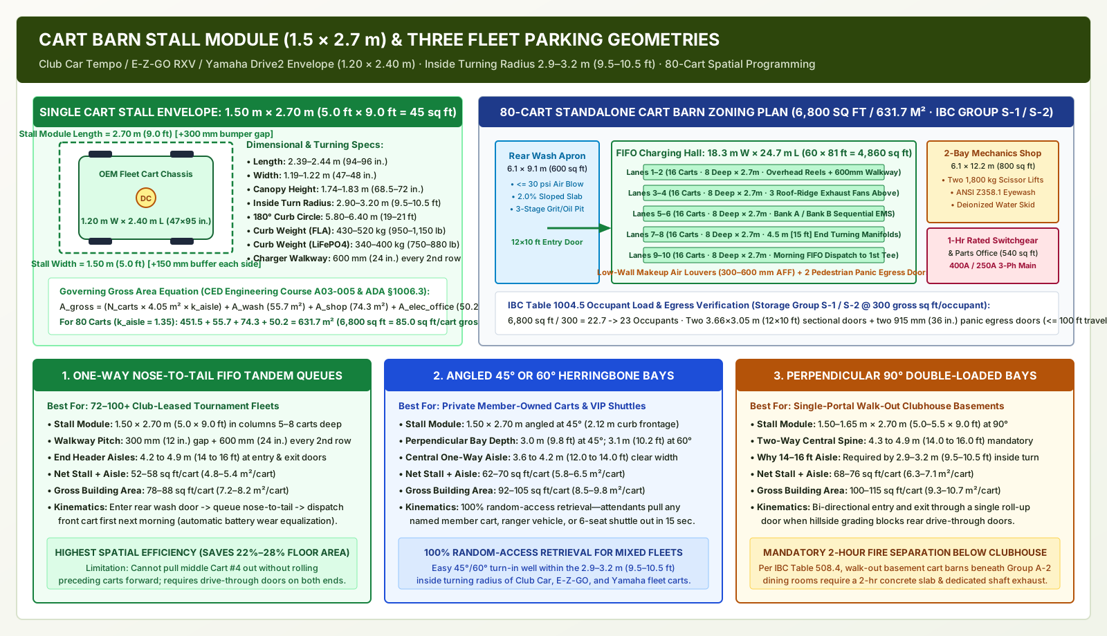
Comparing Three Cart Barn Parking Topologies: FIFO Tandem Queues vs. 45°/60° Herringbone vs. 90° Perpendicular Aisles
How stalls are arranged inside the golf cart storage building depends on whether the facility operates a uniform club-leased fleet with drive-through doors on opposite gable ends, a mixed fleet with member-owned carts requiring individual retrieval, or a single-portal basement beneath the main clubhouse (as programmed in golf clubhouse design: arrival sequence, spike-proof circulation zones, and member-visitor flow):
| Parking Layout Topology | Stall Module & Aisle Geometry | Net Stall + Aisle Area per Cart | Gross Barn Area per Cart (Incl. Wash, Shop & MEP) | Operational Kinematics, Battery Equalization & Best Club Fit |
|---|---|---|---|---|
1. One-Way Nose-to-Tail Tandem Queue Lanes (FIFO Linear Columns, 5–8 Carts Deep) |
1.50 × 2.70 m (5.0 × 9.0 ft) continuous lanes; 600 mm (24 in.) walkway every 2nd lane; 4.2–4.9 m (14–16 ft) transverse end-header aisles at rear entry & front exit doors |
4.8–5.4 m² (52–58 sq ft) |
7.2–8.2 m² (78–88 sq ft) (6,800 sq ft for 80 carts) |
Highest Density & Automatic Battery Wear Equalization: Carts enter the rear wash door after the 18th green and queue nose-to-tail down numbered lanes. The next morning, the front cart dispatches first out the starter door (First-In, First-Out), guaranteeing uniform cycle wear across 100% of a leased 72–100 cart fleet. |
2. Angled Herringbone Bays (45° or 60° Drive-In / Back-Out with One-Way Central Aisle) |
1.50 × 2.70 m stalls angled at 45° (2.12 m [7.0 ft] curb frontage × 3.0 m [9.8 ft] perpendicular bay depth) or 60° flanking a one-way 3.6–4.2 m (12.0–14.0 ft) central drive aisle |
5.8–6.5 m² (62–70 sq ft) |
8.5–9.8 m² (92–105 sq ft) (7,800 sq ft for 80 carts) |
100% Random-Access Retrieval: Attendants can pull out Cart No. 42 for a specific private member, tournament rules official, or course ranger in 15 seconds without moving any other cart. Ideal for private country clubs housing named member carts or 4-to-6-seat hospitality shuttles. |
3. Perpendicular 90° Double-Loaded Bays (Two-Way Central Spine) |
1.50–1.65 m × 2.70 m (5.0–5.5 × 9.0 ft) stalls at 90° on both sides of a 4.3–4.9 m (14.0–16.0 ft) two-way central drive aisle (dictated by the 2.9–3.2 m [9.5–10.5 ft] inside turning radius) |
6.3–7.1 m² (68–76 sq ft) |
9.3–10.7 m² (100–115 sq ft) (8,600 sq ft for 80 carts) |
Single-Portal Walk-Out Clubhouse Basement: Required when hillside grading or under-clubhouse structural bays allow overhead roll-up doors on only one facade, forcing carts to enter, swing 90° into a stall, back out, and exit through the same portal. |
Net Single Stall Area (A_stall_net) = W_stall (1.50 m / 5.0 ft) * L_stall (2.70 m / 9.0 ft) = 4.05 m² (45.0 sq ft)
Charging Hall Area (A_hall) = N_carts * A_stall_net * k_aisle   [where k_aisle = 1.25–1.35 FIFO; 1.45–1.65 Angled/90°]
Gross Cart Barn Footprint (A_gross) = A_hall + A_wash_bay + A_mechanics_shop + A_switchgear_office + A_bag_room_opt
IBC Group S-1 / S-2 Design Occupant Load (N_occ) = ceil( A_gross_sqft / 300 gross sq ft per occupant )
Worked Spatial Programming & IBC Table 1004.5 Egress Calculation (80-Cart Standalone Cart Barn)
Consider an 18-hole championship or daily-fee golf course operating an 80-cart fleet (N_carts = 80)—comprising 72 active tournament carts (36 foursomes × 2 carts per group for a full-field 144-player shotgun start, as analyzed in moving guests through a club on event day) plus 8 spare, ranger, starter, and beverage utility carts (note: 27- and 36-hole resorts scale to 100–140 carts per CED Engineering Course A03-005):
-
Step 1 — Net Parking Stall Footprint (
80 Cartsin10 FIFO Tandem Lanes × 8 Carts Deep):A_stalls_net = 80 carts * 4.05 m² (45.0 sq ft) = 324.0 m² (3,600 sq ft).- Grouping the
10tandem lanes into5paired double-rows (each 3.0 m [10 ft] wide × 21.6 m [72 ft] long) with four600 mm(2.0 ft) interior charger inspection walkways and two600 mmperimeter wall walkways yields a15.6 m(51.2 ft) net bay width, framed inside a standard18.3 m Wide × 24.7 m Long(60 ft × 81 ft) clear-span pre-engineered metal or structural steel bay (451.5 m²/4,860 sq ftcharging hall,k_aisle = 1.35) that includes two4.5 m(15.0 ft) transverse entry and exit turning manifolds at the front and rear overhead doors.
-
Step 2 — Dedicated Wash-Down Bay, Mechanics Shop & Fire-Isolated Switchgear Room:
- Covered 3-Cart Wash-Down Apron & 3-Stage Interceptor Pit (
A_wash_bay):55.7 m²(600 sq ft,6.1 m × 9.1 m[20 ft × 30 ft]) positioned outside the rear return overhead door so wet clippings and wash mist never enter the battery charging hall. - 2-Bay Fleet Mechanics, Tire & Battery Maintenance Shop (
A_mechanics_shop):74.3 m²(800 sq ft,6.1 m × 12.2 m[20 ft × 40 ft]) equipped with two1,800 kg(4,000 lb) turf/golf-car hydraulic scissor lifts, workbenches, a pressurized deionized battery-watering cart station, and a plumbed ANSI/ISEA Z358.1 emergency combination eyewash and drench shower (mandated within 10 seconds / 55 ft [16.8 m] unobstructed travel of any flooded lead-acid battery electrolyte handling or charging zone under OSHA 29 CFR 1926.441(a)(6) and 1910.178(g)). - Electrical Switchgear Room, Spare Parts Cage & Fleet Supervisor Office (
A_switchgear_office):50.2 m²(540 sq ft) separated from the charging hall by a1-hourfire-rated partition with positive air pressurization so corrosive sulfuric acid mist and hydrogen gas never contact main breaker busbars.
- Covered 3-Cart Wash-Down Apron & 3-Stage Interceptor Pit (
-
Step 3 — Total Standalone Cart Barn Gross Building Area (
GBA):A_gross = 4,860 + 600 + 800 + 540 = 6,800 gross sq ft (631.7 m²), or85.0 gross sq ft per cart(7.90 m²/cart) (expanding to 8,100–9,400 gross sq ft when co-locating the 990 sq ft 600-bag high-density mobile storage room fromgolf clubhouse designand a 300–600 sq ft indoor golf simulator studio).
-
Step 4 —
IBC Table 1004.5Occupant Load & Egress Door Verification:- Per DataDrivenAEC (
International Building Code Section 1004.5 and Table 1004.5), motor vehicle storage and repair bays (IBC Occupancy Group S-1 Moderate-Hazard StorageorGroup S-2 Low-Hazard Parking Garage) carry an occupant load factor of300 gross sq ft per occupant(27.87 m²/occupant): N_occ = ceil( 6,800 / 300 ) = ceil( 22.67 ) = 23 occupants.- Provide two
3.66 m W × 3.05 m H(12 ft × 10 ft) insulated motorized sectional overhead doors at opposite ends of the charging hall (enabling one-way drive-through FIFO circulation) flanked by two outward-swinging915 mm(36 in.) pedestrian egress doors equipped with listed panic hardware (keeping maximum common path of egress travel <= 100 ft [30.5 m] per IBC Table 1006.2.1).
- Per DataDrivenAEC (
-
Rule of Thumb (Drive-Through FIFO vs. Basement
90°Layout): Whenever site acreage permits a standalone or walk-out wing with overhead doors on both gable ends, specify 10 nose-to-tail FIFO tandem queue lanes (85 sq ft/cart gross); if topography forces a single-ended basement bay with90°perpendicular stalls and a14 to 16 fttwo-way central spine, increase the structural slab budget by22% to 28%(to 105–110 sq ft/cart gross) and mandate a2-hourfire-rated concrete ceiling assembly (IBC Table 508.4) below upper clubhouse dining rooms.
2. Overnight Fleet Charging Electrical Load, NEC Article 625 Branch Circuits (125% Continuous Rule), and Overhead Cord Drops
Key takeaway: Under NFPA 70 (NEC) Article 625 (§625.41 and §625.42) and NEC §210.20(A), size all golf cart charging branch circuits and feeders at 125% of continuous load (max 16.0 A continuous draw on a 20A breaker), wiring no more than 2 standard 650–900 W (7.8 A @ 120V) chargers per 20A / 120V circuit (or 3 to 4 chargers per 20A / 208–240V 2-pole circuit), mounting chargers on 2.1 to 2.4 m (7 to 8 ft) AFF overhead racks with spring-retractable #10/#12 AWG SOOW cord reels and 5 mA Class A GFCI breakers (NEC §625.54), and deploying a 2-bank sequential load controller (NEC §625.42(A)) to halve 80-cart peak service demand from 400A (121.4 kVA) to 225A–250A (73.9 kVA).
48V Flooded Lead-Acid (FLA) vs. 48V / 51.2V LiFePO4 Lithium-Ion Charger Profiles
Engineering the electrical distribution for a golf cart storage building starts with the AC input current, power factor, and charge-cycle duration of the fleet’s battery chemistry. As documented in the Trojan Battery Maintenance & Charging Guide and OEM fleet charger specifications (Club Car ERIC, Lester Electrical Summit II, and Delta-Q QuiQ), commercial golf fleets operate across three distinct 48V charger profiles:
- 48V Flooded Lead-Acid (
FLA) High-Frequency Smart Chargers (650 W to 900 WDC Output, e.g., six8VTrojan T-875[170 Ah] or four12VT-1275deep-cycle batteries):- DC Output & Multi-Stage Algorithm:
48V DCnominal (rising to 57.1–58.4V during absorption and 60.0–62.0V DC during finishing equalization), delivering13.5 A to 18.0 ADC bulk current. - AC Input Current (
Power Factor >= 0.95, Efficiency88%–92%): Draws7.5 A to 9.0 AAC at120V(900 to 1,080 VA), or3.8 A to 4.5 AAC at208V / 240V(note: legacy ferroresonant transformer chargers draw 10.5 to 12.5 A at 120V with a 0.75–0.82 lagging power factor and should be retired during barn upgrades). - Charge Duration & Electrolysis Heat Loss: Requires
6.5 to 10.0 hoursafter an 18-to-36-hole discharge (75%–80%round-trip energy efficiency; the final20%–25%overcharge/equalization stage electrolyzes water intoH2 + O2gas and dissipates15%–20%of total kWh input as sensible heat).
- DC Output & Multi-Stage Algorithm:
- 48V / 51.2V
LiFePO4Lithium-Ion Standard Overnight Chargers (650 W to 900 W/15A to 18ADC, e.g.,60 Ah to 105 AhLithium Packs):- AC Input Current: Draws
7.2 A to 8.5 AAC at120V(865 to 1,020 VA) or3.5 A to 4.2 AAC at208V / 240V. - Charge Duration & Efficiency: Completes a
0% to 100%Constant-Current / Constant-Voltage (CC/CV) recharge in2.5 to 4.5 hoursat95% to 97%round-trip battery efficiency—slashing annual utility kWh consumption by20% to 25%with zero equalization phase and zero normal hydrogen off-gassing.
- AC Input Current: Draws
- 48V / 51.2V
LiFePO4High-Output Opportunity / Fast Chargers (1,200 W to 1,500 W/25A to 30ADC):- AC Input Current: Draws
11.0 A to 13.5 AAC at120V(1,320 to 1,620 VA) or5.5 A to 6.8 AAC at208V / 240V. - Tournament Turnaround Capability: Replenishes
50%state-of-charge during a45-to-60-minutelunch turnaround between morning and afternoon double-shotgun tournament waves (1.5 to 2.5 hoursfor a full80%depth-of-discharge recovery).
- AC Input Current: Draws
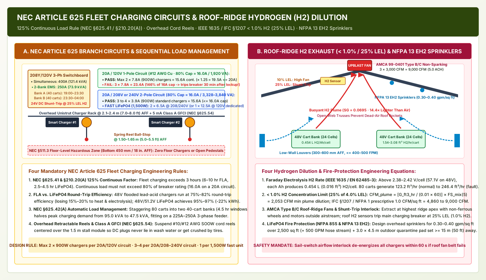
NEC Article 625 (§625.41 / §625.42) and NEC §210.20(A): Why 3 Chargers on a 20A / 120V Circuit Trip at Night
Under NFPA 70 (National Electrical Code) Article 625 (Electric Vehicle Power Transfer System, §625.41 Overcurrent Protection and §625.42 Rating) and NEC Section 210.20(A), any electrical load where maximum current continues uninterrupted for 3 hours or more is classified as a continuous load. Because an 80-cart fleet plugged in between 6:00 PM and 8:00 PM draws continuous bulk current for 3.0 to 8.5 hours, every branch-circuit conductor and overcurrent circuit breaker must be rated at not less than 125% of the continuous charger load (meaning continuous connected load must never exceed 80% of the branch circuit breaker rating):
Minimum Breaker Rating (I_breaker_min) = 1.25 * (N_chargers * I_charger_AC)
Maximum Continuous Branch Circuit Load (I_cont_cap) = 0.80 * I_breaker_rating   [16.0 A on a 20A circuit]
Max Chargers per Branch Circuit (N_max) = floor( (0.80 * I_breaker_rating) / I_charger_AC )
Simultaneous Fleet Charging Feeder (S_chg_kVA) = (N_carts * VA_charger * 1.25) / 1000
3-Phase 208Y/120V Line Current (I_3ph_A) = (S_total_kVA * 1000) / (1.732 * 208 V)
Applying the 16.0 A continuous cap (0.80 × 20A) across standard #12 AWG THHN/THWN-2 copper branch circuits (in 3/4 in. EMT conduit, keeping branch voltage drop <= 2.0%–3.0%) establishes three strict wiring limits:
- Case A — Standard
20A / 120VSingle-Pole Branch Circuit (16.0 A/1,920 VAContinuous Cap):- With standard
7.8 A(900 W) high-frequency FLA orLiFePO4chargers:N_max = floor( 16.0 A / 7.8 A ) = floor( 2.05 ) = 2 chargers maximum per 20A / 120V circuit(2 × 7.8 A = 15.6 A continuous; 15.6 A × 1.25 = 19.5 A <= 20A breaker). - The 3-Charger Nighttime Breaker Trip Failure Mode: When an electrical contractor daisy-chains
3standard120Vreceptacles (3 × 7.8 A = 23.4 Acontinuous, or23.4 × 1.25 = 29.25 Adesign load) onto one20A / 120Vcircuit, the breaker does not trip immediately when an attendant plugs in the third cart—because thermal-magnetic inverse-time breakers (UL 489) hold117%of rated current (23.4 A / 20 A) for20 to 45 minuteswhile the internal bimetallic strip heats up. Thirty minutes after staff lock the cart barn and go home, the breaker trips in the dark, leaving every cart on that circuit uncharged at6:30 AM. - With
1,200 to 1,500 W(11.0 to 13.5 A@120V)LiFePO4Fast Chargers:N_max = floor( 16.0 A / 12.5 A ) = 1 charger-> Strictly1 dedicated 20A / 120V branch circuitper charger (NEC §625.40).
- With standard
- Case B —
20A / 208Vor240VTwo-Pole Branch Circuit (16.0 A=3,328 VA@208Vor3,840 VA@240VContinuous Cap):- Nearly all modern commercial high-frequency golf cart chargers (
Lester Summit II,Delta-Q QuiQ,Club Car ERIC) feature universal auto-ranging100–240V AC(50/60 Hz) power supplies. When wired line-to-line at208Vor240V, a900 Wcharger draws only3.8 A to 4.3 AAC. - A single
20A / 208–240V2-pole circuit legally supplies3 to 4standard900 Wchargers (4 × 3.9 A = 15.6 A <= 16.0 A) or2high-output1,500 W(6.5 A) lithium fast chargers, cutting conduit runs by50%and reducing line voltage drop across25 m(80 ft) charging lanes to< 1.2%.
- Nearly all modern commercial high-frequency golf cart chargers (
| Electrical Engineering Parameter | 48V Flooded Lead-Acid (High-Frequency Smart Charger) | 48V / 51.2V LiFePO4 Lithium (Standard Overnight Charger) | 48V / 51.2V LiFePO4 Lithium (Opportunity Fast Charger) |
|---|---|---|---|
| Rated Output Power & AC Input Current | 650–900 W (7.5–9.0 A @ 120V AC; 3.8–4.5 A @ 208/240V AC; PF >= 0.95) |
650–900 W (7.2–8.5 A @ 120V AC; 3.5–4.2 A @ 208/240V AC; CC/CV) |
1,200–1,500 W (11.0–13.5 A @ 120V AC; 5.5–6.8 A @ 208/240V AC) |
Max Chargers per 20A / 120V Circuit (16.0 A Cont. Cap, NEC §625.41) |
Maximum 2 Chargers (2 × 7.8 A = 15.6 A <= 16.0 A; 3 chargers trip breaker) |
Maximum 2 Chargers (2 × 7.5 A = 15.0 A <= 16.0 A) |
Strictly 1 Charger (1 × 12.5 A = 12.5 A <= 16.0 A; dedicated NEC §625.40 circuit) |
Max Chargers per 20A / 208–240V 2-Pole Circuit (16.0 A Cont. Cap) |
3 to 4 Chargers (4 × 3.9 A = 15.6 A <= 16.0 A) |
3 to 4 Chargers (4 × 3.8 A = 15.2 A <= 16.0 A) |
Maximum 2 Chargers (2 × 6.5 A = 13.0 A <= 16.0 A) |
Recharge Duration (80% DoD) & Round-Trip Efficiency |
6.5 to 10.0 hours (75%–82% round-trip efficiency; 15%–20% lost to heat & H2 electrolysis) |
2.5 to 4.5 hours (95%–97% round-trip efficiency; cuts annual kWh electric bill by 20%–25%) |
1.5 to 2.5 hours full (45–60 min for 50% shotgun lunch turnaround boost) |
80-Cart Fleet Service Demand (208Y/120V 3-Phase, Incl. 26.4 kVA MEP) |
400A Simultaneous (121.4 kVA) | 250A with 2-Bank Sequential EMS (73.9 kVA) |
400A Simultaneous (118.0 kVA) | 225A with 2-or-3-Bank Sequential EMS |
600A Simultaneous (176.4 kVA) | 400A with Automated Load-Shedding EMS |
Worked 80-Cart Main Switchboard & NEC §625.42(A) Sequential Load-Management Calculation
For our 6,800 sq ft Cart Barn housing 80 carts (80 × 950 VA = 76.0 kVA nominal continuous charger load) on a 208Y/120V, 3-Phase, 4-Wire service:
- Unmanaged Simultaneous Charging Feeder Demand (
NEC §215.2(A)(1)125%Continuous Factor):S_charging_design = 80 carts * 0.95 kVA * 1.25 = 95.0 kVA(wired across forty 20A/120V 1-pole circuits [2 carts/circuit] in two 42-space 225A branch subpanels, or twenty 20A/208V 2-pole circuits [4 carts/circuit]).
- Coincident Building Mechanical, Wash-Bay & Lighting Loads (
S_aux):- Roof-ridge explosion-proof exhaust fans (
3 × 1.5 HP = 5.4 kVA) + Wash-bay booster pump and shop air compressor (7.5 HP = 8.2 kVA) + Mechanics scissor lifts, battery-water deionizer, and shop receptacles (6.0 kVA) + High-bay wet-location LED lighting (6,800 sq ft × 0.8 W/sq ft × 1.25 = 6.8 kVA) =26.4 kVA.
- Roof-ridge explosion-proof exhaust fans (
- Total Unmanaged Main Service Rating (
400ASwitchboard):S_total_simultaneous = 95.0 kVA + 26.4 kVA = 121.4 kVA.I_line_3ph = 121,400 VA / (1.732 * 208 V) = 337.0 Amps-> Specify a400A(or 600Awhen future-proofing for100 cartsor1,500 Wopportunity fast chargers)208Y/120V3-Phase Main Switchboard fed by a150 kVApad-mounted transformer.
- Automated 2-Bank Sequential Energy Management System (
NEC §625.42(A)—50%Peak Charger Load Reduction):- Because carts sit parked in the barn for
10.5 to 11.5 hoursovernight (7:00 PM to 6:30 AM) whileLiFePO4packs (2.5–4.5 hr) or moderately discharged FLA packs require under4.5 hoursof active bulk current, installing an automated sequential bank contactor controller (NEC §625.42(A)) partitions the charging subpanels into Bank A (Lanes 1–5 = 40 carts, energized7:00 PM to 11:30 PM) and Bank B (Lanes 6–10 = 40 carts, energized11:30 PM to 4:00 AM, followed by an all-bank finish/equalize top-off window from4:00 AM to 6:00 AMwhen bulk current has already tapered below3.5 A). - Peak charging demand drops by
50%from95.0 kVAto47.5 kVA(total building demand = 47.5 + 26.4 = 73.9 kVA = 205.1 Amps @ 208Y/120V 3-phase), allowing the entire 80-cart barn to operate on a225A to 250A3-phase feeder off an existing clubhouse transformer and cutting monthly utility peak-kW demand charges by40% to 50%.
- Because carts sit parked in the barn for
Overhead Charger Trapeze Racks (2.1–2.4 m AFF), Retractable Cord Reels, and NEC §625.54 Class A GFCI
Floor-mounted charger pedestals or extension cords laid across a cart barn slab get crushed under 1,000 lb cart tires, corroded by battery acid drips, and submerged during floor washdowns. Detail the charging distribution overhead:
- Elevated Unistrut Charger Trapeze (
2.1 to 2.4 m/7.0 to 8.0 ftAFF): Bolt off-board smart chargers onto galvanized steel Unistrut trapeze racks suspended from the roof purlins above the600 mm(24 in.) inspection walkways. Mounting chargers at2.1 to 2.4 mAFF keeps all arcing relays and AC receptacles well above the450 mm(18 in.) floor-level hazardous vapor zone defined inNEC Article 511.3and out of bumper impact range. - Overhead Spring-Retractable Cord Reels (
1.50 to 1.65 m/5.0 to 5.5 ftPendant Stop): Route each charger’s DC output cable (#10 AWGor#12 AWGoil-resistantSOOWcord, or a20A/120V NEMA 5-20Rtwist-lock drop for carts with on-board lithium chargers) through a heavy-duty ratcheting spring-retractable overhead reel centered directly above each1.50 m × 2.70 mstall. Adjust the rubber ball-stop so the DC plug hangs at1.50 to 1.65 m(5.0 to 5.5 ft) above the slab—chest-high for an attendant walking the lane, clear of cart windshields, and completely off the floor. - Mandatory Class A
5 mAGFCI Protection (NEC §625.54&§210.8(B)): Every120Vto240Vreceptacle supplying fleet charging equipment or wash-bay appliances must be protected by a Class A Ground-Fault Circuit-Interrupter (4 to 6 mAtrip threshold perUL 943, matching the wet-zone safety standard in locker room design).
3. Hydrogen (H2) Evolution, < 1.0% LEL Dilution Math, Explosion-Proof Roof Exhaust (IFC §1207 / NFPA 855), and LiFePO4 Fire Protection
Key takeaway: During the final 15% to 20% finish/equalization stage of a 48V (24-cell) flooded lead-acid charge (> 2.38 to 2.42 V/cell), water electrolysis releases 0.454 L (0.016 ft³) of buoyant hydrogen gas (H2, specific gravity 0.0695) per Ah per cell (123.2 to 246.4 ft³/hr across 80 carts); per IEEE 1635, IFC §1207, and NFPA 1 / NFPA 855, dilute H2 below 1.0% by volume (25% of the 4.0% LEL) using floor-level louvers (300–600 mm AFF) and roof-ridge upblast fans (AMCA 99-0401 Type B/C spark-resistant aluminum wheels, 1.0 CFM/sq ft = 4,860 to 9,000 CFM / 5.0 ACH) interlocked with 25% LEL shunt-trip gas detectors, and protect LiFePO4 fleets with NFPA 13 Extra Hazard Group 2 (0.30 to 0.40 gpm/sq ft) overhead sprinklers.
Faraday’s Law of Electrolysis and 80-Cart Hydrogen (H2) Gas Evolution Physics
During the first 80% of a flooded lead-acid (FLA) recharge (the constant-current bulk stage), nearly all electrical energy converts lead sulfate (PbSO4) back into lead dioxide (PbO2) and sponge lead (Pb). However, once battery terminal voltage crosses the gassing voltage threshold of 2.38 to 2.42 V per cell (57.1 to 58.1V on a 48V 24-cell golf cart bank per Trojan Battery), the plates can no longer absorb the full charging current chemically. During the final 1.5 to 3.0 hours of absorption and finishing equalization (at 3.0 to 5.0 A normal finish current, or 8.0 to 10.0 A under a manual equalize cycle or a shorted cell / stuck charger relay), excess current electrolyzes water in the dilute sulfuric acid electrolyte (2 H2O -> 2 H2 [gas] + O2 [gas]).
As established in Critical Power Battery Solutions (Battery Room Ventilation CFM Calculation — IEEE 1635, IFC & NFPA 1) and Greenheck Fan Corporation (Battery Room Ventilation and Hydrogen Gas Dilution):
- Electrochemical Hydrogen Evolution Constant (
Faraday's Law/IEEE 1635/EN IEC 62485-3): Every1.0 Ampere-hour (Ah)of overcharge dissociates0.336 gof water to evolve0.420 to 0.454 liters(0.015 to 0.016 ft³, or0.000268 ft³/min) of pure hydrogen gas (H2) per2Vcell at standard temperature and pressure. - Single-Cart
H2Evolution Rate (24 Series Cellsin a48VGolf Cart):- Normal Finish / Equalization Current (
I_overcharge = 4.0 Aacross24 cells):G_cart_normal = 24 cells * 4.0 A * 0.454 L/(Ah*cell) = 43.58 L/hr (1.536 ft³/hr = 0.0256 CFM of pure H2 per cart).
- Worst-Case Fault / Equalize Surge (
I_overcharge = 8.0 Aacross24 cells):G_cart_fault = 24 cells * 8.0 A * 0.454 L/(Ah*cell) = 87.17 L/hr (3.072 ft³/hr = 0.0512 CFM of pure H2 per cart).
- Normal Finish / Equalization Current (
- Simultaneous 80-Cart Fleet
H2Evolution Rate (G_fleet):- Normal All-Fleet Finish Window:
G_fleet_normal = 80 carts * 1.536 ft³/hr = 122.9 ft³/hr (~123.2 ft³/hr = 3.49 m³/hr = 2.05 CFM of pure H2). - Worst-Case All-Fleet Overcharge:
G_fleet_fault = 80 carts * 3.072 ft³/hr = 245.8 ft³/hr (~246.4 ft³/hr = 6.98 m³/hr = 4.11 CFM of pure H2).
- Normal All-Fleet Finish Window:
The 4.0% Lower Explosive Limit (LEL), < 1.0% Code Dilution Formula, and 1.0 CFM/sq ft Roof Exhaust Sizing
Hydrogen gas in air has a Lower Explosive Limit (LEL / Lower Flammability Limit LFL) of 4.0% by volume (40,000 ppm) and an Upper Explosive Limit (UEL) of 75.0% (Greenheck, Critical Power). Two physical properties make hydrogen inside a golf cart storage building uniquely hazardous compared to propane or gasoline vapors:
- Extreme Buoyancy (
14.4× Lighter Than Air): With a molecular weight of2.016 g/mol(specific gravity = 0.0695relative to air =1.00), releasedH2rises at1.5 to 3.0 m/sstraight to the highest roof ridge peak. Even when the average room-wide concentration is< 0.2%, unventilated purlin bays or ridge peaks can stratify into an explosive> 4.0% H2cloud directly around overhead door motors and high-bay lighting fixtures. - Ultra-Low Ignition Energy (
0.017 mJ): Hydrogen requires just0.017 millijoulesof spark energy to detonate (15 times lower than methane or propane [0.25–0.28 mJ])—an invisible static discharge from a fan belt or an unsealed thermostat contact is sufficient to ignite a roof pocket.
To prevent explosive stratification, International Fire Code (IFC) Chapter 12 (§1207), NFPA 1 / NFPA 855, IEEE Standard 1635 / ASHRAE, and EN IEC 62485-3 enforce two governing airflow calculations:
Per-Fleet H2 Generation (G_fleet_ft3_hr) = N_carts * N_cells (24) * I_overcharge_A * 0.016 ft³/(Ah*cell)
IEEE 1635 Theoretical 1% Dilution (CFM_1pct) = G_fleet_ft3_hr / (0.01 * 60 min/hr) = G_fleet_ft3_hr / 0.60
Stratification-Safe Plume Dilution (CFM_plume) = CFM_1pct * FS_mixing (5.0 per EN 62485-3 / ASHRAE)
Prescriptive Fire Code Exhaust (Q_code_cfm) = max( A_charging_sqft * 1.0 CFM/sq ft , (Volume_ft3 * 5.0 ACH) / 60 )- Worked Hydrogen Dilution & Sensible Heat Exhaust Calculation (
6,800 sq ftCart Barn,4,860 sq ftCharging Hall,16.0 ft[4.88 m] Mean Roof Height =108,800 ft³Building Volume):- Check 1 —
IEEE 1635/EN 62485-3Plume Dilution to< 1.0% H2(25% of 4.0% LEL):- Theoretical
1.0%dilution at worst-case8.0 Afleet overcharge (G_fleet_fault = 246.4 ft³/hr):CFM_1pct = 246.4 / (0.01 * 60) = 410.7 CFM. - Multiplying by the
FS_mixing = 5.0air-mixing safety factor (accounting for non-uniform dilution and rising plume buoyancy):CFM_plume = 410.7 * 5.0 = 2,053.5 CFM (969 L/s)minimum continuous plume dilution airflow.
- Theoretical
- Check 2 — Prescriptive
IFC §1207/NFPA 1Floor-Area Rate (1.0 CFM / sq ft):- Across the
4,860 sq ft(451.5 m²) battery charging hall:Q_ifc = 4,860 sq ft * 1.0 CFM/sq ft = 4,860 CFM (2,294 L/s).
- Across the
- Check 3 — Whole-Barn
5.0 ACHVolumetric Sweep & Charger Heat Removal (24,570 BTU/hr):- Eighty
900 Wchargers operating at90%efficiency reject80 × 90 W = 7,200 W(24,570 BTU/hr) of sensible equipment heat (plus ~18,000 BTU/hr of battery electrochemical heat during equalization = 42,570 BTU/hr total). - Sizing for
5.0 Air Changes per Hour (ACH)across the108,800 ft³barn volume yieldsQ_5ACH = (108,800 * 5.0) / 60 = 9,067 CFM-> Specify three (3) roof-ridge upblast centrifugal exhaust fans rated at3,000 CFM(1,416 L/s) each =9,000 CFM(4,248 L/s) total capacity:- Base Lead Fan (
Fan 1 = 3,000 CFM): Runs continuously whenever the charging switchboard is energized (exceeding the 2,053.5 CFM worst-case 5× IEEE 1635 H2 dilution requirement). - Peak Lag Fans (
Fans 2 & 3 = +6,000 CFM, Total9,000 CFM): Stage on automatically during the evening bulk/equalization window (7:00 PM – 4:00 AM), whenever indoor temperature exceeds85°F(29.4°C), or immediately upon any10% LEL(0.40% H2) gas sensor alarm.
- Base Lead Fan (
- Eighty
- Check 1 —
Five Mandatory Explosion-Proof Roof Exhaust & H2 Shunt-Trip Interlock Details
Whereas interior clubhouse locker rooms (engineered in locker room design: negative-pressure ventilation, wet-zone separation, benches, and plinth lockers) extract heavy, moisture-laden air at 0.50 cfm/sq ft from shower stalls, a golf cart storage building must capture rising hydrogen gas (NEC Class I, Division 1/2, Group B) at the highest roof apex without introducing an ignition source:
- Highest-Point Roof-Ridge Extraction & Open-Web Trusses (
Zero Dead-Air Pockets): Mount all exhaust fan roof curbs directly along the structural gable ridge peak (within 300 mm [12 in.] vertically of the highest interior roof surfaceper Greenheck). Never install a flat lay-in acoustic ceiling that creates an unventilated attic above the charging floor. Frame the roof with open-web steel bar joists (or punch 150 mm [6 in.] diameter eave-to-ridge equalization holes near the top web of solid Z-purlins) so buoyantH2glides unimpeded up the roof pitch into the ridge fan intakes. - Spark-Resistant
AMCA 99-0401 Type B or Type CUpblast Fans & Out-of-Airstream Motors: Specify rooftop upblast centrifugal exhaust fans manufactured to AMCA Standard 99-0401 Type B or Type C spark-resistant construction (non-ferrous aluminum backward-inclined impeller wheel, non-ferrous shaft rubbing ring, and static-conducting drive belts). Place the drive motor inside a ventilated motor compartment completely isolated from the exhaust airstream, or specify a listed Explosion-Proof Class I, Division 1, Group B (Hydrogen) motor (standard Group C/D motors rated for propane or gasoline vapors cannot arrest a Group B hydrogen flame front). - Floor-Level Motorized Makeup Air Louvers (
300 to 600 mm/12 to 24 in.AFF): Install storm-proof architectural intake louvers with motorized spring-return fail-open dampers along the bottom300 to 600 mm(12 to 24 in.) of the exterior walls (sized at <= 400 to 500 FPM [2.0–2.5 m/s] net free-area velocity -> 18 to 22 sq ft [1.7–2.0 m²] of net free louver area for 9,000 CFM). Cool outdoor air enters at slab level, sweeps diagonally upward through the under-seat battery bays of all 80 carts, and exits out the roof ridge. - Two-Stage Roof-Peak
H2Gas Detectors &25% LELMain-Breaker Shunt-Trip Interlock (IFC §1207/NFPA 855): Mount catalytic-bead or solid-state Hydrogen (H2) Gas Sensors along the roof ridge (spaced every 12 to 15 m [40 to 50 ft], 3 to 4 sensors per 6,800 sq ft barn) wired to a supervised safety controller:- Stage 1 Low Alarm (
10% LEL=0.40% H2/4,000 ppm): Forces all three roof exhaust fans to100%speed (9,000 CFM), drives all perimeter makeup dampers full open, and illuminates an exterior amber warning strobe. - Stage 2 High Alarm (
25% LEL=1.00% H2/10,000 ppm): Energizes the24V DCshunt-trip coil on the main400A / 250Afleet charging circuit breaker, instantly cutting AC power to all 80 battery chargers to halt water electrolysis at its source while locking the roof exhaust fans on high speed and sounding an85 dBAexterior horn/strobe.
- Stage 1 Low Alarm (
- Loss-of-Airflow Differential Pressure (
Sail Switch) Interlock: Wire a differential air-pressure switch across the lead roof exhaust fan so that if a fan belt snaps or a louver actuator jams closed, the battery charging subpanels automatically de-energize after a60-secondfault delay—guaranteeing the fleet can never charge inside an unventilated building.
LiFePO4 Lithium-Ion Fleet Fire Protection: NFPA 13 Extra Hazard Group 2 (0.30–0.40 gpm/sq ft) and Quarantine Pads
When a club upgrades its fleet to 48V / 51.2V LiFePO4 lithium-ion packs, normal daily electrolysis drops to zero (allowing normal idle exhaust to step down to ASHRAE 62.1 storage/parking ventilation of 0.15 to 0.75 CFM/sq ft for heat removal), but lithium-ion thermal runaway fire protection (NFPA 855, FM Global Data Sheet 5-33, and NFPA 13) governs building life safety:
- Overhead Fire Sprinkler Density (
NFPA 13 Extra Hazard Group 2 [EH2]): Size automatic wet-pipe (or dry-pipe / pre-action in freezing northern climates) overhead fire sprinklers to NFPA 13 Extra Hazard Group 2 (0.30 to 0.40 gpm/sq ft[12.2 to 16.3 mm/min] over a2,500 sq ft[232 m²] remote design area) using high-temperature286°F(141°C)K-11.2orK-14.0upright sprinkler heads, plus a500 GPM(1,890 L/min) hose-stream allowance (1,250 to 1,500 GPM total water supply duration for 90 to 120 minutes). Although water does not extinguish an internal lithium cell cathode reaction,0.30–0.40 gpm/sq fthigh-density cooling absorbs radiant heat flux and prevents an isolated BMS/cell fault on one cart from igniting theABSbody panels and rubber tires of the adjacent79carts. - Exterior Damaged-Cart Quarantine Pad (
>= 15 m/50 ftSetback): Cast a dedicated3.0 m × 4.5 m(10 ft × 15 ft) exterior concrete quarantine pad located>= 15 m(50 ft) from any building wall, propane tank, or tree line, and stage a long-handle emergency tow bar beside the cart barn roll-up door so any cart exhibiting BMS over-temperature faults or white electrolyte vapor (which releases flammable H2, CO, CH4, and trace HF gas during thermal runaway) can be towed outdoors immediately.
4. Wash-Down Apron Hydraulics and 3-Stage Grit, Grass-Clipping, and Oil-Water Interceptor Pit Engineering
Key takeaway: Pre-clean returning golf carts at a Stage 0 dry compressed-air blow-off station regulated at <= 30 psi (OSHA 29 CFR 1910.242(b)) to strip 45% to 55% of dry grass clippings before wet rinsing, wash carts on a 6.1 m × 9.1 m (20 × 30 ft) curbed concrete pad sloped at 2.0% to 2.5% (wet PTV >= 45) using 40 to 65 psi @ 4 to 8 GPM low-pressure hoses (never > 1,500 psi), and route wash water through a 3-stage interceptor train: a 1.5–3.0 mm Type 316 stainless wedge-wire grass basket, a 500 to 1,000 gal dual-chamber weir-baffled silica sand settling basin (20–30 min HRT), and an API / EN 858-1 coalescing oil-water separator (<= 10–15 mg/L) or 85%–90% closed-loop biological water recycling skid.
Why Golf Cart Wash Water Destroys Standard Plumbing—and How <= 30 psi Dry Air Pre-Cleaning Cuts Grass Loading by 50%
Every golf cart returning from an 18-hole round carries three incompatible contaminants on its tires, wheel wells, pedal box, and undercarriage, as documented by the Golf Course Superintendents Association of America (GCM / GCSAA Golf Course Wash Pad Design Guide):
- Buoyant Wet Turfgrass Clippings (
Specific Gravity 0.85 to 1.02, blade length3 to 25 mm): Unlike sand, fresh Poa annua, bentgrass, and bermudagrass blades float or remain neutrally buoyant in water. If washed into a standard4 in.(100 mm) floor drain or conventional P-trap, grass blades bypass gravity sediment sumps, mat across pipe bends, and undergo anaerobic bacterial fermentation within48 to 72 hours—generating corrosive, foul-smelling hydrogen sulfide (H2Srotten-egg gas) and spiking Biological Oxygen Demand (BOD). - Heavy Angular Silica Bunker & Topdressing Sand (
Specific Gravity 2.65, particle size150 to 1,000 µm): Rapidly settles out in low-velocity horizontal sewer lines, cementing inside pipe inverts until the drain blocks solid. - Trace Hydrocarbons & Foliar Turf Chemicals: Chassis grease, transaxle oil drips, and residual nitrogen/phosphorus fertilizers and fungicides washed off tires cannot legally discharge into surface ponds, creeks, or municipal storm sewers under Clean Water Act / EPA NPDES illicit-discharge regulations.
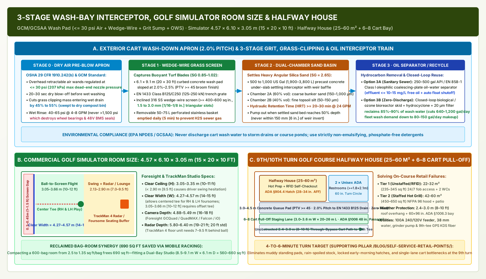
To prevent interceptor overload before water ever touches the fleet, GCM / GCSAA wash-pad engineering specifies a Stage 0 Dry Compressed-Air Pre-Blow Station at the approach edge of the wash apron:
- OSHA
<= 30 psi(207 kPa) Regulated Air Wands: Suspend two overhead retractable compressed-air hoses fed from the mechanics shop air compressor through a lockable pressure regulator capped at30 psi(207 kPa) maximum dead-ended nozzle pressure (OSHA 29 CFR 1910.242(b)) (matching the Stage 1 golfer boot-wash air wand specification ingolf clubhouse design). 45% to 55%Grass-Clipping Reduction: In20 to 30 secondsper cart, attendants blow dry grass clippings, pine needles, and loose bunker sand off the rubber floor mat, pedal recess, and bag well into a dry sweep trough for direct turf composting—cutting the mass of organic clippings entering the wet wash-water interceptor by50%.
Wash-Down Pad Slope (2.0%–2.5%), Low-Pressure Hose Booms (40–65 psi @ 4–8 GPM), and EN 1433 Class B125/C250 Trench Grates
Immediately past the dry blow-off zone, construct a 3-Cart Reinforced Concrete Wash-Down Containment Pad (6.1 m × 9.1 m / 20 ft × 30 ft = 55.7 m² / 600 sq ft):
- Why High-Pressure Washers (
> 1,500 psi) Are Prohibited on Electric Golf Carts: Using a2,500 to 3,500 psiindustrial pressure washer drives water past sealed wheel bearings, transaxle input shafts, steering rack boots, and under-seat48Vmotor controller / lithium BMS enclosures. Specify overhead360°rotary swing-boom hose drops delivering40 to 65 psi(2.8 to 4.5 bar) at4.0 to 8.0 GPM(15 to 30 L/min) fitted with automatic spring-shutoff rubber nozzles. Washing an 80-cart fleet (1.5 to 2.0 minutesper cart at6.0 GPM=9 to 12 gallons[34 to 45 L] per cart) consumes720 to 960 US gallons per day(2,725 to 3,635 L/day) with a peak simultaneous 3-hose flow rate ofQ_wash_peak = 3 × 8.0 GPM = 24.0 GPM(1.51 L/s). - Containment Curb,
2.0% to 2.5%Four-Way Pitch &UK HSE PTV >= 45Broom Texture: Pour a150 mm(6 in.) reinforced concrete slab boxed on three sides by a100 to 150 mm(4 to 6 in.) monolithic containment curb and a rolled entry/exit drive-over berm so zero wash water escapes onto the surrounding asphalt (and zero outside stormwater runs onto the wash padper GCM / GCSAA). Pitch the slab at2.0% to 2.5%(1/4 to 5/16 in. per linear foot) toward a central300 mm(12 in.) wide Type 316 stainless steel or ductile-iron linear trench drain rated to EN 1433 Load Class B125 (125 kN/28,100 lbf) or Class C250 (250 kN/56,200 lbf) (identical to the vehicular drain load classes detailed inpatio drainage system for clubhouse terraces: pedestal pavers vs. sloped mortar and trench drains). Finish the concrete wearing surface with a medium-coarse transverse broom texture achieving a wet Pendulum Test ValuePTV >= 45 to 55(Four-S Slider 96) under UK Health and Safety Executive (HSE Slips and Trips) guidelines.
Daily Fleet Wash Water Volume (V_day_gal) = N_carts * Q_hose_gpm * t_rinse_min
Peak Wash Effluent Flow Rate (Q_peak_gpm) = N_active_hoses * Q_hose_gpm
Stage 2 Grit Sump Working Volume (V_sump_gal) = Q_peak_gpm * HRT_min (20 to 30 min) * FS_sludge (1.5)
Closed-Loop Net Freshwater Makeup (V_makeup_gal) = V_day_gal * (1 - R_recycle [0.85 to 0.90])
The Three-Stage Grit, Grass-Clipping, and Oil-Water Interceptor Train
Effluent entering the central wash-pad trench drain must pass through three sequential separation stages before sanitary sewer discharge or closed-loop reuse:
| Interceptor Stage | Target Contaminant & Physical Principle | Quantitative Sizing & Material Specification (80-Cart Fleet) | Preventive Maintenance & Disposal Protocol |
|---|---|---|---|
| Stage 1: Inclined Wedge-Wire Grass-Clipping Screen & Lift-Out Basket | Buoyant & Suspended Turfgrass Blades (SG = 0.85–1.02, 3–25 mm length) via positive mechanical screening above waterline |
>= 400 to 600 sq in. (0.26–0.39 m²) Type 316 Stainless Steel Inclined Wedge-Wire Screen (1.5 to 3.0 mm [1/16–1/8 in.] triangular non-blinding slots) discharging into a removable 50 to 75 L (13–20 gal) perforated stainless clipping basket inside the primary trench trough. |
Daily (End of Evening Shift — 5 Minutes): Lift perforated basket, drain free water for 2 min, and dump fresh clippings onto the turf compost pile before anaerobic H2S fermentation begins. |
| Stage 2: Dual-Chamber Weir-Baffled Silica Sand & Silt Settling Basin | Heavy Angular Silica Bunker Sand (SG = 2.65, 150–1,000 µm) & Topsoil Silt (50–150 µm) via Stokes' Law gravity sedimentation (v_h < 0.05 ft/s) |
500 to 1,000 US Gallons (1,900–3,800 L) precast reinforced concrete under-slab tank divided by an over-under concrete weir baffle into Chamber 2A (60% vol — coarse sand) and Chamber 2B (40% vol — fine silt), delivering HRT >= 20 to 30 min at 24 GPM peak flow under 36 × 36 in. diamond-plate covers. |
Monthly / Quarterly (When Sand Bed Reaches 50% Depth): Pump or shovel settled sand/silt slurry (never allow settled silica sand within 150 mm [6 in.] of the weir invert). |
| Stage 3A: Coalescing-Plate Oil-Water Separator (Sanitary Sewer Tie-In) | Free-Floating & Dispersed Hydrocarbons (SG = 0.80–0.92, chassis grease, gear/hydraulic oil) via oleophilic plate coalescence |
250 to 500 US Gallons (950–1,900 L) API / EN 858-1 Class I Coalescing-Plate Oil-Water Separator rated for >= 25–35 GPM, achieving effluent free oil <= 10 to 15 mg/L (ppm) with an automatic float shutoff valve and 50 mm (2 in.) atmospheric vent. |
Quarterly: Skim trapped oil into a licensed waste-oil drum and rinse removable oleophilic media packs with warm low-pressure water; use strictly non-emulsifying detergents. |
| Stage 3B: Closed-Loop Biological / Ozone Wash-Water Recycling Skid | Dissolved Organics (BOD), Residual Fines (> 20 µm) & Odor Bacteria via aerobic digestion, hydrocyclone & multimedia filtration |
300 to 500 gal aerated bioreactor tank dosed with hydrocarbon/turf-digesting microbes (or ozone oxidation) + centrifugal hydrocyclone + 20 µm multimedia/activated-carbon filter, reclaiming 85% to 90% of wash water back to the hose booms. |
Cuts net freshwater draw from 800 gal/day down to 80–120 gal/day (evaporation/carryout makeup); backwash filter weekly and check dissolved oxygen monthly. |
5. Co-Located Club Operational Spaces: Commercial Golf Simulator Room Size and 9th/10th Turn Golf Course Halfway House
Key takeaway: Frame co-located teaching and clubfitting studios to a commercial golf simulator room size of 4.57 m W × 6.10 m D × 3.05 to 3.35 m H (15 ft × 20 ft × 10 to 11 ft = 27.9 m² / 300 sq ft clear bay) so tall golfers swing a 45.5 in. driver without ceiling hesitation and both camera (16–18 ft depth) and floor-radar (20 ft depth) launch monitors track centered right- and left-handed play; at the 9th/10th turn, replace muddy, weather-exposed huts with a 25 to 60 m² (270 to 650 sq ft) golf course halfway house served by a PTV >= 45 concrete queue apron and a 6 to 8 cart parallel pull-off staging lane (ADA Chapter 10 §1006).
Commercial Golf Simulator Room Size (4.57 m × 6.10 m × 3.05 m / 15 × 20 × 10 ft Clear Swing Envelope)
As demonstrated in our clubhouse spatial programming analysis (golf clubhouse design: arrival sequence, spike-proof circulation zones, and member-visitor flow), converting a 600-bag member storage room from fixed static shelving (2.5 sq ft/bag = 1,680 sq ft) to high-density mobile carriages (1.35 sq ft/bag = 990 sq ft) reclaims 690 sq ft (64.1 m²) of conditioned floor space directly adjacent to the Pro Shop and Cart Barn. Likewise, newly constructed standalone golf cart storage buildings frequently frame a walk-out course-side wing or second-story mezzanine to house 1 to 2 indoor simulator bays for winter PGA instruction, custom clubfitting, and rain-delayed tournament play.
However, partitioning a simulator room to standard 2.44 to 2.74 m (8.0 to 9.0 ft) office ceiling heights or narrow 3.05 m (10.0 ft) widths creates an unusable commercial bay. Per Foresight Sports (Complete Golf Simulator Room Setup & Minimum Dimensions Guide) and TrackMan Golf (Commercial Golf Simulator Studio Specifications), specifiers must enforce three clear interior dimensions (measured clear of 50 mm acoustic wall panels, ceiling baffles, HVAC ducts, sprinkler heads, and the 38 to 65 mm [1.5–2.5 in.] raised hitting turf platform):
- Clear Ceiling Height (
3.05 to 3.35 m/10.0 to 11.0 ftCommercial Standard;2.74 m/9.0 ftBare Minimum for Shorter Swings):- A
1.88 m(6 ft 2 in.) golfer swinging a standard1,156 mm(45.5 in.) driver on an upright plane reaches a peak clubhead arc elevation of2.70 to 2.90 m(8 ft 10 in. to 9 ft 6 in.) above the top surface of the hitting mat (which already sits 50 mm [2.0 in.] above the concrete slab). - Any clear ceiling height below
2.90 m(9.5 ft) triggers involuntary “indoor ceiling hesitation” (Foresight Sports), causing tall members to flatten their follow-through or gouge ceiling baffles with60°lob wedges. Specify3.05 m(10 ft 0 in.) minimum clear ceiling height (increasing to 3.20–3.35 m [10.5–11.0 ft] when mounting ceiling-suspended overhead launch monitors like the Foresight Falcon or TrackMan iO and WUXGA/4K short-throw laser projectors at 2.85–3.00 m [9.3–9.8 ft] AFF).
- A
- Clear Bay Width (
4.27 to 4.57 m/14.0 to 15.0 ftfor Center-Tee RH/LH Play;3.05 to 3.66 m/10.0 to 12.0 ftOffset Single-Handed):- In a commercial country club foursome, right-handed (
RH) and left-handed (LH) players alternate shots on every hole. A narrow3.05 to 3.66 m(10.0 to 12.0 ft) enclosure forces the hitting tee to be offset450 to 600 mm(18 to 24 in.) to one side of the screen centerline so the driver head does not strike the rear wall on the backswing—meaning left-handed players cannot use the bay without physically sliding the hitting strip. - Framing a
4.27 to 4.57 m(14.0 to 15.0 ft) clear room width places the hitting tee dead-center on the impact screen with2.13 to 2.29 m(7.0 to 7.5 ft) of radial swing clearance on both sides, accommodating simultaneous RH and LH play without adjustments.
- In a commercial country club foursome, right-handed (
- Clear Room Depth by Launch Monitor Technology (
4.88 to 5.49 m[16–18 ft] Camera vs.6.10 m[20 ft] Dual Doppler Radar):- Photometric Camera & Overhead Optical Units (
Foresight GC3, GCQuad, QuadMAX, Falcon, andTrackMan iO): Measure ball launch and spin optically within300 to 450 mm(12 to 18 in.) of clubhead impact. Total clear depth required is4.88 to 5.49 m(16.0 to 18.0 ft), comprising:D_buffer = 0.30 to 0.45 m(1.0 to 1.5 ft) tensioned air gap behind the impact screen (so 175 mph [280 km/h] ball strikes deflect the woven polyester screen without rebounding off the structural concrete wall),D_flight = 2.44 to 3.05 m(8.0 to 10.0 ft) tee-to-screen ball flight distance (close enough that 56°–60° sand/lob wedge shots strike the upper screen rather than the ceiling baffle), andD_swing_lounge = 2.13 to 2.44 m(7.0 to 8.0 ft) rear backswing envelope plus spectator safety buffer (maintaining a mandatory >= 3.05 m [10.0 ft] total clearance from the hitting tee to the front edge of any rear bar counter or lounge seating).
- Floor-Mounted Dual Doppler Radar Units (
TrackMan 4, TrackMan Studio Specs): Because the floor unit sits behind the hitting mat and tracks 3D ball flight between the tee and the screen, specify5.80 to 6.40 m(19.0 to 21.0 ft,6.10 m[20.0 ft] standard) total room depth:0.30–0.45 m(1.0–1.5 ft) rear screen gap +3.05–3.66 m(10.0–12.0 ft) ball-to-screen flight +2.13–2.90 m(7.0–9.5 ft) ball-to-TrackMan-4 rear radar placement.
- Photometric Camera & Overhead Optical Units (
| Simulator Studio Tier | Clear Width (W) |
Clear Depth (D) |
Clear Height (H) |
Net Floor Area & Launch Monitor Compatibility |
|---|---|---|---|---|
| 1. Compact Single-User / Offset Practice Bay (Camera / Overhead Only) | 3.05 – 3.66 m (10.0 – 12.0 ft) (offset tee for RH or LH) |
4.27 – 4.88 m (14.0 – 16.0 ft) (0.3 m gap + 2.4 m flight + 1.8 m swing) |
2.74 – 2.90 m (9.0 – 9.5 ft) minimum |
13.0 – 17.8 m² (140 – 192 sq ft) | Fits Foresight GC3 / GCQuad / QuadMAX floor units (zero rear spectator seating) |
| 2. Country Club Standard Single Bay (Center-Tee RH/LH + Foursome Lounge) | 4.27 – 4.57 m (14.0 – 15.0 ft) (dead-center tee for RH & LH play) |
5.49 – 6.10 m (18.0 – 20.0 ft) (includes 1.8–2.4 m rear lounge zone) |
3.05 – 3.35 m (10.0 – 11.0 ft) clear below projector |
25.0 – 27.9 m² (270 – 300 sq ft) | Universal fit for TrackMan 4, TrackMan iO, and Foresight Falcon / QuadMAX |
3. Dual-Bay Teaching & Clubfitting Studio (Fits Reclaimed 690 sq ft Bag Room) |
8.53 – 9.14 m (28.0 – 30.0 ft) (two 14–15 ft bays + STC 45 divider) |
6.10 – 6.70 m (20.0 – 22.0 ft) (includes shared fitting bench & bar) |
3.20 – 3.66 m (10.5 – 12.0 ft) |
52.0 – 61.2 m² (560 – 660 sq ft) | Fits directly inside the 690 sq ft saved by high-density mobile bag racking |
9th/10th Turn Golf Course Halfway House (25–60 m² / 270–650 sq ft) and 6–8 Cart Pull-Off Staging Lane
Our supporting pillar selling drinks and balls from a point on the course establishes the four operational failures that plague an unengineered retail hut between holes:
- Uncovered bottles and snacks exposed to direct sun or driving rain;
- A standing queue pad of bare soil or slick wet timber that turns into mud underfoot;
- A locked serving hatch during early-morning or twilight hours when golfers actually pass; and
- No accountable system for spoiled stock or cashless payment failures.
When an 18-hole routing brings the 9th green directly back to the clubhouse perimeter, players use the exterior 9th-Hole Turn Window built into the 19th-hole grill prep line (Node 5 in golf clubhouse design: arrival sequence, spike-proof circulation zones, and member-visitor flow). However, on classic out-and-back links routings (where the 9th green and 10th tee sit 800 m to 1.5 km from the clubhouse) or sprawling resort courses, architects must build a permanent golf course halfway house (Turn Kiosk & Comfort Station) engineered to process two overlapping foursomes (8 players in 4 golf carts) within a 4-to-6-minute turn window (CED Engineering Course A03-005 and U.S. Access Board ADA Chapter 10 §1006):
- Two Architectural Program Tiers (
25 to 60 m²/270 to 650 sq ftGross Building Area):- Tier 1 — Unstaffed / Hybrid
24/7RFID Self-Service & Restroom Pavilion (22 to 32 m²/235 to 345 sq ft): Directly solves the “locked hatch during early/late tee times” failure mode in selling drinks and balls from a point on the course. Comprises two single-occupant unisex ADA restrooms (each >= 1.83 m × 2.13 m [6.0 × 7.0 ft = 42 sq ft] with a 1,525 mm [60 in.] wheelchair turning circle per ADA §603.2.1 and R11/PTV >= 45 unglazed porcelain tile) flanking a conditioned10 to 14 m²(110 to 150 sq ft) grab-and-go alcove accessed via a member RFID proximity fob or tee-time QR code. Houses glass-front commercial reach-in beverage coolers (35°F–38°F[1.7°C–3.3°C] with cellular IoT temperature/spoilage telemetry), golf ball/glove dispensing, ice/water bottle filling, and cashless POS terminals beneath a2.4 to 3.0 m(8.0 to 10.0 ft) deep wrap-around roof overhang (keeping sun and driving rain completely off the stock and transaction screen). - Tier 2 — Staffed Short-Order Hot-Grill Halfway House & Covered Porch (
42 to 60 m²/450 to 650 sq ft): Comprises an18 to 24 m²(195 to 260 sq ft) commercial turn kitchen (high-speed convection/impingement oven, flat-top griddle under an NFPA 96 Type I exhaust hood, under-counter refrigeration, ice maker, 3-compartment sink + hand sink, and 6 m² dry/cold stockroom), two exterior serving hatches incorporating a915 mm(36 in.) wide ×710 to 865 mm(28 to 34 in.) high loweredADA §904.4transaction counter, men’s and women’s ADA restrooms (12 to 16 m²), and a12 to 18 m²(130 to 195 sq ft) covered high-top standing porch.
- Tier 1 — Unstaffed / Hybrid
- Eliminating the Muddy Queue Pad (
UK HSE PTV >= 45&1.5%–2.0%Pitch toEN 1433 Class B125Drain):- To permanently eliminate the muddy soil or slippery wet timber standing pad identified in selling drinks and balls from a point on the course and UK HSE Slips and Trips, never step golfers off a cart onto grass or unsealed wood boards in front of the hatch.
- Pour a
3.0 to 4.5 m(10.0 to 15.0 ft) deep broom-finished concrete or20 mm(3/4 in.) structural porcelain paver queue apron (wet Pendulum Test Value PTV >= 45–55,ANSI A326.3 Exterior Wet DCOF >= 0.60) pitched at1.5% to 2.0%(<= 1:48[2.08%] maximum cross-slope along the accessible route perADA §403.3) into a perimeter Type 316 stainless steelEN 1433 Load Class B125(125 kN) slot or trench drain (matching the terrace drainage details inpatio drainage system for clubhouse terraces).
6 to 8 CartParallel Pull-Off Staging Lane, Through-Bypass Path &ADA Chapter 10 §1006Passage:- Parking even two golf carts on a standard
2.4 m(8.0 ft) single-lane cart path completely blocks trailing foursomes skipping the turn, beverage restocking Gators, and emergency ranger vehicles. - Grade a dedicated parallel or
45°sawtooth cart pull-off staging lane accommodating6 to 8 golf carts(2 full foursome waves[4 carts] at the counter +1 wave[2 carts] in restrooms +1–2utility/ranger carts), measuring3.0 to 3.6 m(10.0 to 12.0 ft) wide ×20.0 to 26.0 m(65 to 85 ft) long, immediately alongside an unobstructed2.4 to 3.0 m(8.0 to 10.0 ft) one-way through-bypass cart path leading to the 10th tee. - Per U.S. Access Board ADA Chapter 10 (§238.3 and §1006 Golf Car Passages and Weather Shelters), connect the cart pull-off staging lane to the serving hatch and restroom thresholds via a continuous
>= 1.22 m(48 in., expanding to1.52 m[60 in.] where curbs, bollards, or handrails exist) flush golf car passage, and include at least one covered1.52 m × 2.44 m(60 in. × 96 in.) level weather-shelter cart bay (ADA §1006.3).
- Parking even two golf carts on a standard
- Underground Utility Trench & 9th-Tee GPS Pre-Order Fiber Synchronization:
- Feed the halfway house via a single underground utility trench carrying a
100A,240/120Vsingle-phase (or 208Y/120V3-phase) electrical feeder, a38 mm(1.5 in.) potable water service, a50 mm(2.0 in.) sanitary sewer grinder-pump force main tied back to the clubhouse sanitary sewer, and single-mode fiber-optic cable. Linking the 9th-tee GPS cart screen (or geofenced mobile ordering app) to the halfway house Kitchen Display System (KDS) fires hot food orders12 minutesbefore the foursome holes out on the 9th green—so orders are bagged and waiting at the hatch90 secondsbefore the carts pull into the staging lane.
- Feed the halfway house via a single underground utility trench carrying a
Simulator Clear Bay Area (A_sim) = W_clear (4.57 m / 15 ft) * D_clear (6.10 m / 20 ft) = 27.87 m² (300.0 sq ft)
TrackMan 4 Radar Depth (D_radar) = D_screen_gap (0.35 m) + D_flight (3.35 m) + D_rear_radar (2.40 m) = 6.10 m (20.0 ft)
Halfway House Pull-Off Length (L_pulloff) = N_staged_carts (6 to 8) * L_stall_pitch (3.20 m / 10.5 ft) = 19.2 to 25.6 m (63–84 ft)
Total Halfway House Corridor Width (W_turn_corridor) = W_bypass (2.7 m) + W_pulloff (3.3 m) + W_queue_pad (3.6 m) = 9.6 m (31.5 ft)
Method and sources
Golf cart chassis dimensions (1.19–1.22 m × 2.39–2.44 m / 47–48 in. × 94–96 in., 2.90–3.20 m [9.5–10.5 ft] inside turning radius), net single stall modules (1.50 × 2.70 m / 5.0 × 9.0 ft = 45 sq ft), gross golf cart storage building area multipliers (78–115 sq ft/cart across FIFO tandem queues, 45°/60° herringbone bays, and 90° perpendicular aisles), 6,800 sq ft 80-cart spatial programming, and 9th-hole golf course halfway house siting are synthesized from CED Engineering (An Introduction to Golf Clubhouse Design, Course No. A03-005). Federal accessibility dimensions for 48 in. (1,220 mm) minimum golf car passages (60 in. [1,525 mm] with barriers) and 60 × 96 in. (1,525 × 2,440 mm) clear level spaces within course weather shelters and turn stops follow the U.S. Access Board (ADA Accessibility Standards Guide — Chapter 10: Golf Courses, Sections 238 and 1006). Storage occupancy load factors (300 gross sq ft per occupant for IBC Group S-1/S-2) and egress door calculations follow the International Building Code via DataDrivenAEC (How to Calculate Occupant Load — IBC Section 1004.5 and Table 1004.5).
Deep-cycle 48V flooded lead-acid (six 8V or four 12V) vs. 48V/51.2V LiFePO4 battery charging profiles, gassing voltage thresholds (2.38–2.42 V/cell), and 125% continuous branch-circuit and feeder sizing (max 2 standard 900W chargers per 20A/120V circuit at 16.0A continuous cap, 3–4 per 20A/208–240V circuit, 2-bank sequential load management, and 5 mA Class A GFCI protection) reference Trojan Battery Company (Battery Maintenance & Charging Guide) and NFPA 70 (National Electrical Code Article 625 and Section 210.20(A)). Hydrogen gas evolution rates (0.454 L / 0.016 ft³ H2 per Ah per cell), the < 1.0% H2 (25% of 4.0% LEL) dilution equation (CFM = G / [0.01 × 60]), prescriptive 1.0 CFM/sq ft mechanical exhaust rates, AMCA 99-0401 Type B/C spark-resistant roof-ridge upblast fans, and 10% LEL / 25% LEL shunt-trip gas detector interlocks follow Greenheck Fan Corporation (Battery Room Ventilation) and Critical Power Battery Solutions (Battery Room Ventilation CFM Calculation — IEEE 1635, IFC §1207 & NFPA 1). Fleet wash-pad slopes (2.0%), <= 30 psi dry compressed-air pre-cleaning (50% clipping reduction), inclined wedge-wire grass-clipping screens, dual-chamber silica sand settling sumps, coalescing oil-water separators, and wet slip-resistance thresholds (PTV >= 45) cite the Golf Course Superintendents Association of America (GCM Golf Course Wash Pad Guide) and the UK Health and Safety Executive (HSE Slips and Trips), while commercial golf simulator room size envelopes (4.57 × 6.10 × 3.05 m / 15 × 20 × 10 ft) follow Foresight Sports (Complete Golf Simulator Room Setup) and TrackMan Golf (Commercial Simulator Studio Specifications), all accessed 26 October 2026. Updated October 2026.