Golf course bunkers fail in playability and storm recovery when specifiers order local mason or silica sand based on visual whiteness or a loose 0.25 to 1.00 mm quarry label without verifying grain angularity, silt-and-clay limits, mineral hardness, and subgrade isolation. When a bunker sand contains rounded, high-sphericity grains with pocket penetrometer resistance below 1.8 kg/cm² (tons/sq ft), descending approach shots bury past their equator into “fried-egg” plugged lies and sand slumps off steep bunker faces during routine irrigation. Conversely, when combined silt and clay (< 0.05 mm) exceeds 3.0%—or when storm runoff erodes unlined clay subgrades into the sand bed—saturated hydraulic conductivity ($K_{sat}$) collapses below the 20 in./hr (508 mm/h) minimum threshold, floating fines to the surface that bake into 1/8 to 1/4 in. (3 to 6 mm) crusts or cement-like slabs requiring complete excavation.
Engineering consistent ball lies and rapid storm evacuation across an 18-hole facility requires coupling accredited physical soil testing (ASTM F1632, Klute 1986, and the Brown & Thomas 1986 bunker evaluation series) with a sealed bunker liner and perforated bunker drainage underdrain network:
- USDA / ASTM F1632 Particle Size Gradation (
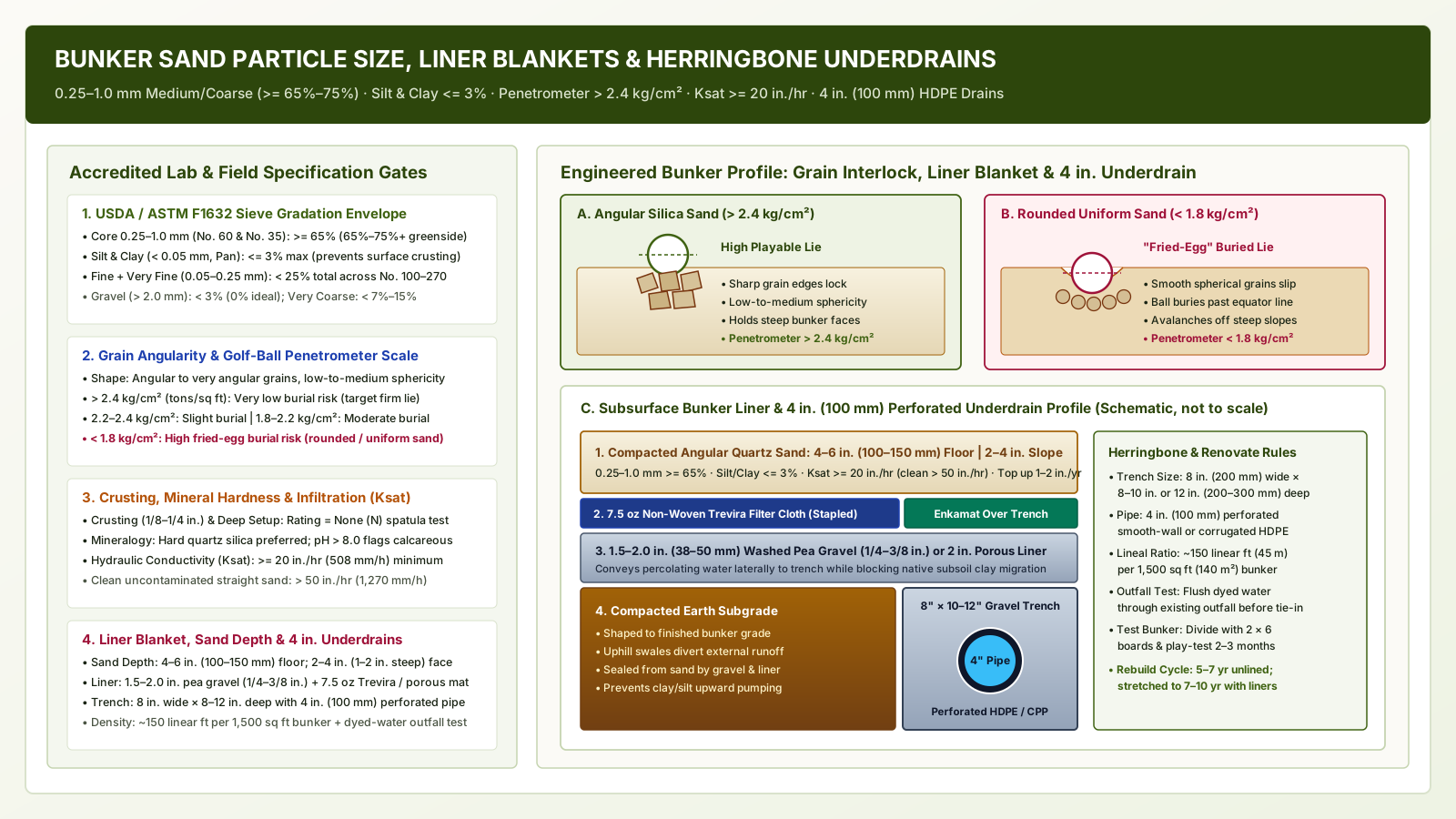
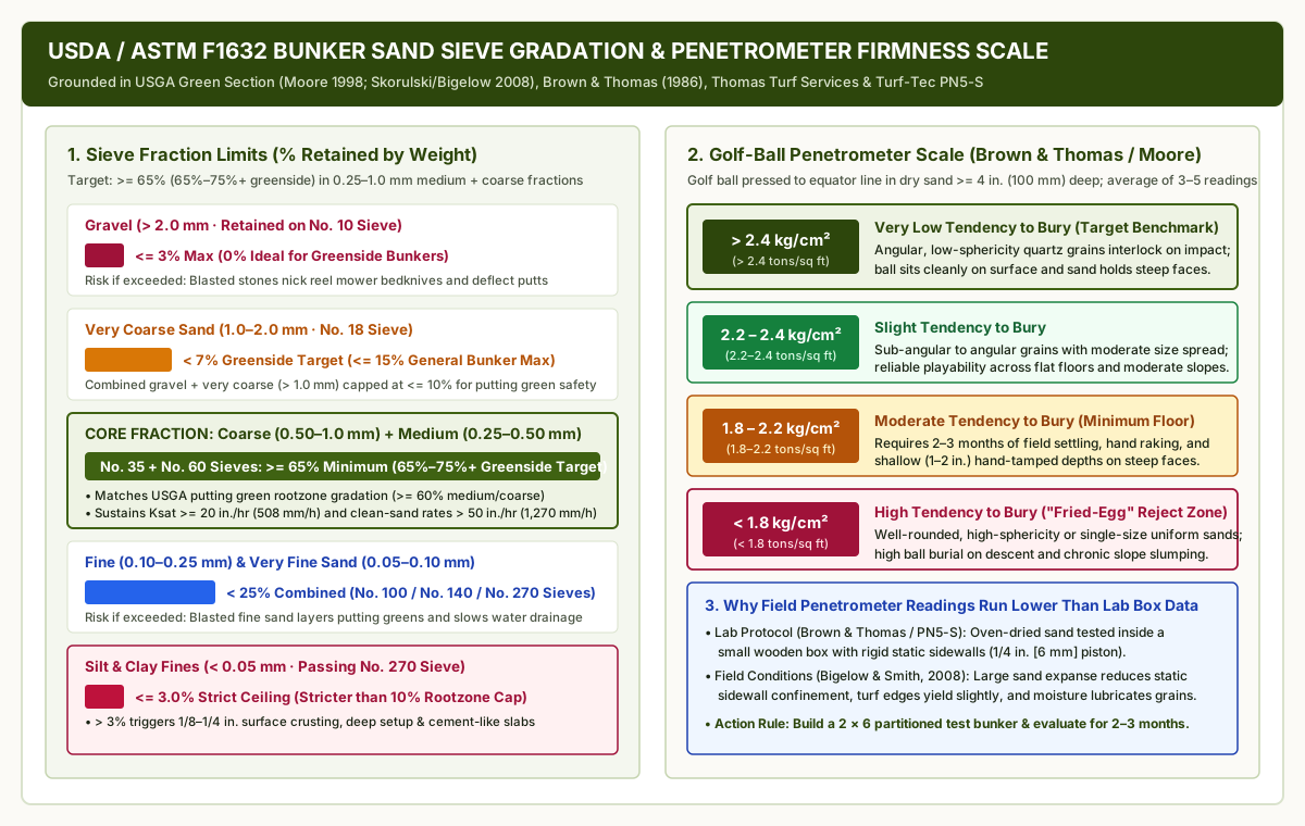
0.25–1.0 mm >= 65%&Silt + Clay <= 3%): Require at least65%(> 65%) of particles—and65% to 75%+in greenside bunkers—within the medium (0.25–0.50 mm, No. 60 sieve) and coarse (0.50–1.00 mm, No. 35 sieve) sand fractions (USGA Green Section, Moore 1998;Thomas Turf Services / Labosport, J.C. Thomas 2019;Turf-Tec PN5-S Specification). Cap combined fine and very fine sand (0.05–0.25 mm) at< 25%, restrict combined silt and clay (< 0.05 mm, passing No. 270 sieve) to<= 3.0%(three times stricter than the<= 10%very-fine/silt/clay allowance in putting green rootzones), and limit gravel (> 2.0 mm, No. 10 sieve) to< 3%(0%ideal) with very coarse sand (1.0–2.0 mm, No. 18 sieve) at< 7%greenside (<= 15%general bunker limit) so blasted sand neither nicks reel mower bedknives nor seals adjacent putting green rootzones. - Angular Low-Sphericity Grain Geometry & Pocket Penetrometer Firmness (
>= 1.8–2.2 kg/cm²Floor,> 2.4 kg/cm²Ideal): Select hard quartz (silica) sand (pH <= 8.0, free of calcareous carbonate dissolution) with angular to very angular edges and low-to-medium sphericity that interlock under impact. Verify an unconfined compressive strength of> 2.4 kg/cm²(tons/sq ft) for a very low tendency to bury (2.2 to 2.4 kg/cm²slight;1.8 to 2.2 kg/cm²moderate; reject< 1.8 kg/cm²high burial risk) using the modified golf-ball pocket penetrometer test (Brown & Thomas 1986;Moore 1998 Table 1), an overnight spatula crusting and deep setup rating of None (N), and a laboratory saturated hydraulic conductivity ($K_{sat}$) of>= 20 in./hr(508 mm/h) minimum (> 50 in./hr[1,270 mm/h] typical for clean uncontaminated sand). - Bunker Liner Blankets, Differential Sand Depth &
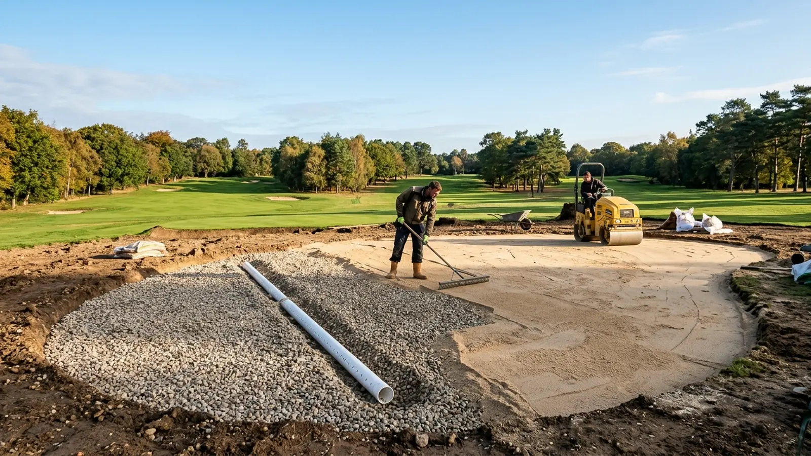
4-Inch(100 mm) Herringbone Underdrains: Isolate the sand bed from native subsoil clay using the USGA Enhanced Bunker Drainage Method (O'Brien 1999)—a1.5 to 2.0 in.(38 to 50 mm) washed pea-gravel blanket (1/4 to 3/8 in.stone) beneath7.5 oznon-wovenTrevirageotextile stapled to the subgrade and bridged withEnkamatover the drain slots—or a2.0 in.(50 mm) sprayed/poured porous aggregate or polymer liner. Evacuate percolating storm water through8 in.(200 mm) wide by8 to 10 in.(200–250 mm) or8 × 12 in.(200 × 300 mm) deep gravel trenches housing4 in.(100 mm/ DN100) perforated HDPE/CPP pipe (~150 linear ft[45 m] per1,500 sq ft[140 m²] bunker) in a herringbone, Y, or cross-slope smile pattern connected to a dyed-water-verified outfall, topped with4 to 6 in.(100–150 mm) of compacted sand on flat floors and2 to 4 in.(1 to 2 in.on steep flashed faces) of hand-tamped sand on slopes.
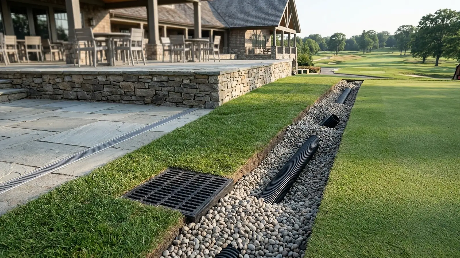
Within our sports facilities engineering series—which pairs on-site inspection checklists in changing rooms: benches, hooks and water on the tile with mechanical exhaust and wet-core drainage tolerances in locker room design: negative-pressure ventilation, wet-zone separation, benches, and plinth lockers—this guide governs open-profile aggregate infiltration and subsurface pipe collection inside course hazards. Where impermeable clubhouse decks rely on 2.0% membrane slopes, 3 to 5 mm open pedestal joints, and IPC Section 1106 bi-level deck drains detailed in patio drainage system for clubhouse terraces: pedestal pavers vs. sloped mortar and trench drains, and maintenance compounds intercept sand and turf clippings washed off bunker rakes and utility vehicles in the 3-stage grit trap specified in golf cart storage building design: stall dimensions, NEC 625 fleet charging, and hydrogen exhaust, bunker construction depends on vertical pore percolation through unamended sand directly into gravel-lined collector trenches.
| Engineering Parameter | Greenside Bunker Target Specification | General / Fairway Bunker Acceptable Limit | USGA Putting Green Rootzone Reference | Primary Failure Mode if Violated |
|---|---|---|---|---|
Core Medium + Coarse Sand (0.25–1.0 mm · No. 60 & No. 35) |
>= 65% minimum (65%–75%+ preferred) |
>= 65% minimum across 0.25–1.0 mm |
>= 60% medium + coarse sand in rootzone mix |
Excess uniform fine or coarse fractions destabilize ball lies or slow drainage |
Silt & Clay Fines (< 0.05 mm · Passing No. 270 Sieve) |
<= 3.0% strict ceiling |
<= 3.0% strict ceiling |
Up to <= 10% combined very fine sand, silt & clay |
> 3% triggers 1/8–1/4 in. surface crusting, deep setup & pore sealing |
Fine + Very Fine Sand (0.05–0.25 mm · No. 100–270) |
< 25% combined (match or coarser than green) |
<= 25% combined |
<= 20% fine (0.10–0.25 mm) + <= 5% very fine |
Blasted fine sand forms a surface seal on putting greens, blocking infiltration |
Gravel (> 2.0 mm · No. 10) & Very Coarse (1.0–2.0 mm · No. 18) |
Gravel < 3% (0% ideal); Very Coarse < 7% |
Gravel <= 3%; Very Coarse <= 15% |
Gravel <= 3%; combined > 1.0 mm <= 10% |
Blasted particles > 2.0 mm nick reel mower bedknives and deflect putts |
Grain Shape & Pocket Penetrometer (Brown & Thomas) |
Angular / low sphericity; > 2.4 kg/cm² target |
Angular / sub-angular; >= 1.8–2.2 kg/cm² min |
Sub-angular to sub-rounded, medium sphericity | Rounded high-sphericity sand (< 1.8 kg/cm²) causes plugged "fried-egg" lies |
Crusting / Setup Rating & Mineralogy (pH) |
None (N) spatula test; Quartz silica (pH <= 8.0) |
None (N) to Light (L); Quartz silica preferred |
Quartz silica preferred; carbonate dissolution risk | Calcareous limestone (pH > 8.0) crushes under rakes & cements drain lines |
Saturated Hydraulic Conductivity (Ksat · Klute 1986) |
>= 20 in./hr (508 mm/h) min; > 50 in./hr clean |
>= 20 in./hr (508 mm/h) min (no upper cap) |
6 to 24 in./hr (152–610 mm/h) controlled range |
Subgrade clay washout drops Ksat, ponding water & forming cement slabs |
| Compacted Sand Depth & Underdrain Trench | 4–6 in. floor; 1–2 in. / 2–4 in. face + liner |
4–6 in. floor; 2–4 in. slope + 4 in. pipe in 8×10 in. trench |
12 in. (300 mm) compacted rootzone over gravel |
Deep loose slope sand avalanches; shallow floor sand exposes liner to clubs |
USDA and ASTM F1632 Bunker Sand Particle Size Gradation (0.25–1.0 mm Core Envelope & Greenside Rootzone Compatibility)
Specify a bunker sand containing at least 65% (> 65%)—and 65% to 75%+ in greenside bunkers—within the 0.25 to 1.00 mm medium-to-coarse USDA fraction (ASTM F1632), with combined silt and clay (< 0.05 mm) capped at <= 3.0%, fine plus very fine sand (0.05–0.25 mm) below 25%, gravel (> 2.0 mm) below 3% (0% ideal), and greenside very coarse sand (1.0–2.0 mm) below 7%.
As James Francis Moore (Director of the USGA Green Section Construction Education Program) establishes in the USGA Green Section Record guide to selecting bunker sand (Jan/Feb 1998), particle size screening is the mandatory first filter in evaluating a candidate quarry product, determined by an accredited physical soil testing laboratory using American Society for Testing and Materials (ASTM F1632) sieve procedures and United States Department of Agriculture (USDA) grain size classifications (Turf & Soil Diagnostics, 2002). Unlike a putting green rootzone mix—which blends sand with peat or amendments to retain moisture and nutrients for turf roots—a bunker contains unamended straight sand exposed directly to rainfall, foot traffic, and mechanical raking.

Why Greenside Bunker Gradation Must Match or Exceed Putting Green Rootzone Coarseness
A critical agronomic rule highlighted by both the USGA Green Section (Moore, 1998) and James C. Thomas, C.P.Ag. (co-developer of the Brown & Thomas 1986 bunker evaluation protocol at Thomas Turf Services / Labosport) is that golfers continuously blast large volumes of greenside bunker sand onto adjacent putting surfaces. This airborne transfer creates two distinct mechanical and hydraulic boundaries between greenside bunker sand and putting green rootzone sand:
- Preventing Fine-Over-Coarse Surface Sealing on Putting Greens (
0.05–0.25 mm < 25%): In soil physics, placing a coarser sand over a finer rootzone mix does not impede water entry, matching the rule used for selecting putting green topdressing sand. However, if a club installs a greenside bunker sand that is significantly finer in gradation than the putting green’s rootzone mixture, repeated explosion shots deposit a fine-textured surface layer across the collar and putting surface. Because very fine sand (0.05–0.10 mm) behaves hydraulically like silt and clay, this fine blast layer seals the upper rootzone, retards water infiltration, and forces the maintenance staff to perform extra core aerification on the affected sections of the green—backfilling the aerifier holes with coarsely graded sand to restore vertical drainage (Moore, 1998, p. 9;Turf & Soil Diagnostics, 2002). - Eliminating Mower Bedknife Nicks and Putt Deflections (
> 2.0 mm < 3%&1.0–2.0 mm < 7%): At the coarse end of the sieve stack, particles larger than2.00 mm(retained on the No. 10 sieve) are classified as gravel. When blasted onto closely mown putting surfaces, gravel and excessive very coarse sand (1.0–2.0 mm, No. 18 sieve) fail to settle into the turf canopy: they deflect putts off line, slow pace of play as golfers brush debris from putting lines, and nick precision reel mower blades and bedknives (Moore, 1998, pp. 9–10; Skorulski & Bigelow, 2008, p. 8). Consequently,Thomas Turf Services(J.C. Thomas, 2019) restricts ideal greenside bunker sand to< 3%gravel (0%ideal) and< 7%very coarse sand (1.0–2.0 mm) (matching the<= 10%combined> 1.0 mmcap in USGA rootzone sand), whereas general bunker specifications (Turf-Tec PN5-S) allow up to<= 15%very coarse sand in fairway hazards located well away from greenside reels. - Why the Silt and Clay Cap (
<= 3%) Is Stricter Than Rootzone Sand (<= 10%): A USGA putting green rootzone sand can contain>= 60%medium and coarse sand, up to20%fine sand (0.10–0.25 mm), up to5%very fine sand (0.05–0.15 mm), and up to10%combined very fine sand, silt, and clay (J.C. Thomas, 2019). Bunker sand requires a stricter<= 3%ceiling on combined silt (0.002–0.05 mm) and clay (< 0.002 mm) because even a4% to 6%silt/clay fraction in bare, unrooted sand migrates upward during evaporative drying to cement surface grains into a hard crust.
| USDA Soil Fraction | Particle Diameter (mm) | U.S. Standard Sieve (ASTM F1632) | Greenside Bunker Target (Thomas Turf / USGA) | General Bunker Spec (Turf-Tec PN5-S) | USGA Green Rootzone Sand Benchmark |
|---|---|---|---|---|---|
| Gravel (Fine Gravel) | > 2.00 mm (2.0–4.0 mm) |
Retained on No. 10 (2.00 mm) |
< 3% (0% gravel-free ideal) |
<= 3% maximum |
<= 3% gravel; <= 10% combined > 1.0 mm |
| Very Coarse Sand | 1.00 – 2.00 mm |
Retained on No. 18 (1.00 mm) |
< 7% (prevents mower pickup) |
<= 15% maximum |
Combined with gravel <= 10% total |
| Coarse Sand | 0.50 – 1.00 mm |
Retained on No. 35 (0.50 mm) |
> 65% combined (65%–75%+ target) across 0.25–1.00 mm |
>= 65% combined (Coarse + Medium Grade) |
>= 60% combined medium and coarse sand |
| Medium Sand | 0.25 – 0.50 mm |
Retained on No. 60 (0.25 mm) |
|||
| Fine Sand | 0.10 – 0.25 mm (or 0.15–0.25 mm) |
Retained on No. 100 (0.15 mm) / No. 140 (0.106 mm) |
< 25% combined across 0.05–0.25 mm |
<= 25% combined (Medium Fine + Very Fine) |
<= 20% in fine (0.10–0.25 mm) range |
| Very Fine Sand | 0.05 – 0.10 mm (or 0.05–0.15 mm) |
Retained on No. 270 (0.053 mm) |
<= 5% very fine; <= 10% with silt & clay |
||
| Silt & Clay (Pan Fines) | < 0.05 mm (Silt 0.002–0.05; Clay < 0.002) |
Passing No. 270 (< 0.053 mm Pan) |
<= 3.0% maximum |
<= 3.0% maximum |
Included inside <= 10% combined fine cap |
Coefficient of Uniformity ($C_u$), Particle Size Spread, and Angle of Repose
While Dr. James B. Beard’s Turf Management for Golf Courses (2002) notes that a narrowly graded sand is agronomically clean, Turf & Soil Diagnostics (2002) and the 2008 Purdue University / USDA-ARS study of 20+ bunker sands in the USGA Green Section Record demonstrate why an overly narrow, single-size gradation undermines playability. When all grains share virtually the same diameter (a very low Coefficient of Uniformity, $C_u = D_{60} / D_{10}$, where $D_{60}$ and $D_{10}$ are the sieve diameters passing 60% and 10% of the sample by weight), particles lack smaller bridge grains to lock the pore matrix together.
As Moore (1998, p. 10) and Dr. Cale Bigelow (2008, pp. 7–8) explain, sands that are highly uniform in size and rounded in shape behave like a bucket of ball bearings: they shift underfoot, avalanche down steep erosion-prone bunker slopes, and allow golf balls to bury deeply. Conversely, a sand with a balanced spread of particle dimensions within the 0.25–1.00 mm envelope and angular grain geometry achieves a higher Angle of Repose ($\theta$)—measured in the laboratory by pouring dry sand into a cone and calculating $\theta = \arctan(2H / D_{\text{base}})$ from the cone apex height ($H$) and mean base diameter ($D_{\text{base}}$). Coarser-textured, angular sands with a wider particle size distribution stack to a narrower base and taller cone apex, directly increasing slope stability on flashed bunker faces (Skorulski & Bigelow, 2008, p. 8).
Particle Shape (Angularity & Sphericity) and Pocket Penetrometer Resistance to “Fried-Egg” Lies
Select bunker sand with angular to very angular grain edges and low-to-medium sphericity that achieves a laboratory golf-ball pocket penetrometer reading of > 2.4 kg/cm² (tons/sq ft) for very low burial tendency—or at minimum 1.8 to 2.4 kg/cm²—and reject well-rounded, high-sphericity sands reading < 1.8 kg/cm².
Passing a 0.25 to 1.00 mm sieve analysis never guarantees that a sand will play firmly. As Moore (1998, pp. 9–10) cautions, two sands with identical sieve gradations can play at opposite extremes—one rock-hard and the other unplayably soft—because of differences in particle shape, which soil laboratories classify under a microscope or macroscope (ASTM F1632) across two independent geometric axes:
- Angularity (Edge Sharpness): Graded from very angular (numerous sharp, jagged, well-defined edges and corners), angular, sub-angular, and sub-rounded to well rounded (smooth, worn surfaces typical of wind-blown dune or river-washed sands).
- Sphericity (Overall Grain Form): Graded from low sphericity (elongated, flat, or tabular particles) through medium sphericity to high sphericity (nearly spherical, ball-shaped grains).
Here, the engineering requirement for bunker sand diverges sharply from putting green rootzone sand (Thomas Turf Services, 2019). In a putting green rootzone, agronomists specify sub-angular to sub-rounded grains with medium sphericity because highly angular grains pack too tightly under foot and mower traffic and their sharp edges can mechanically abrade turfgrass roots. In a sand bunker, however, angular to very angular grains with low-to-medium sphericity are preferred: when a golf ball strikes the sand on a steep angle of descent, the sharp corners and flat facets interlock against adjacent grains, arresting downward penetration and holding the sand in place on steep bunker faces (Moore, 1998, p. 10; J.C. Thomas, 2019; Turf-Tec PN5-S). Keep in mind the playability balance noted by Moore: an extremely angular, crushed sand can produce a surface that plays firmer than some club memberships prefer, whereas a well-rounded, high-sphericity sand slips apart on impact, creating chronic “fried-egg” buried lies and sliding down bunker faces during rainfall or irrigation.
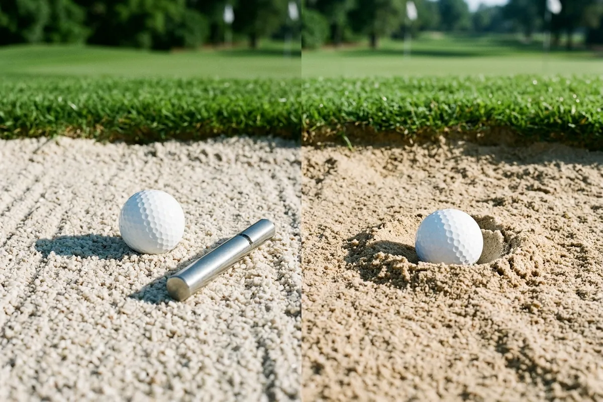
Modified Golf-Ball Pocket Penetrometer Protocol (Brown & Thomas 1986 / PN5-S)
To quantify ball-burial resistance before purchasing thousands of tons of aggregate, accredited physical soil testing laboratories (Turf & Soil Diagnostics, 2002; Thomas Turf Services, 2019) and superintendents use the modified golf-ball pocket penetrometer method developed by Dr. Kirk W. Brown and James C. Thomas at Texas A&M University (Golf Course Management, Vol. 54, July 1986, pp. 64–70) and published in Moore (1998, Table 1, p. 10) and the Turf-Tec International Sand Penetrometer (PN5-S) standard operating procedure:
- Instrument Configuration: The
PN5-SSand Penetrometer features a plated cylindrical body (3/4 in. × 6-3/8 in.[19 × 162 mm], net weight10 oz[283 g]) housing a calibrated spring and a1/4 in.(6 mm) diameter ground stainless-steel loading piston fitted with an actual golf ball marked with a horizontal center (equator) line. The direct-reading barrel scale measures unconfined compressive strength from0.25 to 4.5 kg/cm²(numerically equivalent totons/sq ft) in0.25 kg/cm²increments, with a sliding red friction ring that holds peak load. - Step-by-Step Measurement Procedure:
- Prepare a level bed of dry sand at least
4 inches(100 mm) thick (in the laboratory, a standard volume of oven-dried or air-dried sand is placed in a rigid test vessel and stirred to a uniform loose state). - Slide the red indicator ring down flush against the knurled handle.
- Grip the knurled handle and position the attached golf ball vertically against the sand surface.
- Press downward evenly until the sand surface reaches the center equator line of the golf ball (pressing the ball halfway into the sand).
- Read the unconfined compressive strength in
kg/cm²(tons/sq ft) on the lower side of the red indicator ring (the edge closest to the knurled handle). - Repeat the test at least
3 timesin the field (Turf-Tec PN5-S) or5 timesin an accredited laboratory (Bigelow, 2008, p. 6), discarding extreme outliers to compute the mean reading.
- Prepare a level bed of dry sand at least
| Pocket Penetrometer Reading (kg/cm² or tons/sq ft) | Fried-Egg Burial Tendency (Brown & Thomas 1986 / Moore 1998 Table 1) | Typical Grain Angularity & Sphericity Profile | Field Playability & Slope Behavior |
|---|---|---|---|
> 2.4 kg/cm² |
Very Low Tendency to Bury (Target Benchmark) | Angular to very angular grains; low-to-medium sphericity; interlocking size spread | Ball sits up cleanly after descent; holds steep flashed bunker faces; very firm playability |
2.2 to 2.4 kg/cm² |
Slight Tendency to Bury | Angular to sub-angular grains; low-to-medium sphericity | Consistent firm lies across bunker floors and moderate slopes; minimal washout |
1.8 to 2.2 kg/cm² |
Moderate Tendency to Bury | Sub-angular grains or narrower particle size distribution | Acceptable after 2–3 months of compaction; requires shallow hand-tamped depths on steep faces |
< 1.8 kg/cm² |
High Tendency to Bury ("Fried-Egg" Prone) | Well-rounded to rounded grains; high sphericity ("ball-bearing" dune/river sand) | Frequent buried lies on approach shots; slumps down bunker faces during rain and irrigation |
Why Laboratory Penetrometer Readings Exceed Field Bunker Measurements (2 × 6 Test Bunker Rule)
In the 2008 USGA Green Section Record interview with Dr. Cale Bigelow (Purdue University) and Dr. Douglas Smith (USDA-ARS National Soil Erosion Research Laboratory), researchers evaluated more than 20 commercially available bunker sands and identified a critical calibration gap between laboratory reports and field bunkers:
- Static Sidewall Confinement in the Lab Box: In the laboratory, the penetrometer is pushed (either by hand or via a drill-press assembly) into a relatively small quantity of oven-dried sand held inside a small wooden box with rigid static sidewalls. Those rigid walls prevent lateral grain displacement at the boundaries.
- Unconfined Field Expanse and Moisture Lubrication: In an actual
1,500 sq ftgolf course bunker, the large volume of sand greatly reduces static sidewall forces; even when tested near a bunker lip, the surrounding turf and soil edge exhibit some mechanical “give.” Furthermore, field bunkers experience continuous fluctuations in moisture content, which acts as a particle lubricant that promotes grain slippage depending on particle size distribution and sand depth (Bigelow, 2008, p. 7).
Consequently, while laboratory penetrometer data accurately ranks the relative firmness among candidate sands (a sand testing firmer in the lab will play firmer in the field), field penetrometer measurements will read lower than the laboratory certificate. To bridge this gap before ordering 1,500 to 3,000 tons of sand, follow the two-stage USGA verification protocol (Moore, 1998, p. 12; Bigelow, 2008, p. 7):
- Stage 1 — Accredited Laboratory Screening (
1-GallonDry Sample,2–3 Weeks): Submit a1-gallon(3.8 L) dry sample of each prospective sand to an accredited physical soil testing laboratory (2 to 3 weeksturnaround; historically< $200per sample in Moore’s 1998 USGA guide) to screen out candidates that fail gradation (0.25–1.0 mm >= 65%,silt/clay <= 3%), penetrometer (>= 1.8–2.4+ kg/cm²), crusting (None), or infiltration (>= 20 in./hr). - Stage 2 — Partitioned On-Course Test Bunker (
2 × 6Boards for2–3 Months): Narrow the shortlist to2 or 3lab-approved sands and install them inside an on-course practice or test bunker divided into three compartments using2 × 6lumber boards. Maintain and irrigate the partitioned test bunker for at least2 to 3 monthsso the sands undergo real-world wetting, compaction, and raking before superintendents and players make the final procurement decision.
Crusting vs. Setup Resistance, Mineral Weathering (pH > 8.0 Calcareous vs. Quartz Silica), and Saturated Hydraulic Conductivity ($K_{sat}$)
Specify hard quartz (silica) sand (pH <= 8.0) rated None (N) for both thin surface crusting (1/8 to 1/4 in.) and deep setup on the overnight laboratory spatula test, with a saturated hydraulic conductivity ($K_{sat}$) of at least 20 in./hr (508 mm/h) and clean-sand initial rates exceeding 50 in./hr (1,270 mm/h).
Surface Crusting (1/8 to 1/4 in.) vs. Deep Setup & The Overnight Spatula Test
Golfers and maintenance crews frequently group all hard, post-rain bunker surfaces under a single complaint, but soil physicists distinguish two separate cementation mechanisms (J.C. Thomas, 2019; Moore, 1998, p. 10; Turf & Soil Diagnostics, 2002):
- Surface Crusting (
1/8 to 1/4 in./3 to 6 mmShell): Crusting is the formation of a thin, brittle, stiff layer of dried sand across the top1/8 to 1/4 inchof the bunker—physically analogous to the upper crust of a pie shell. It occurs when silt and clay particles (< 0.05 mm) suspended in rain or irrigation water migrate to the surface during evaporation and bind the top grains together. - Deep Setup (Full Wetting-Depth Cementation): Setup is the formation of a thick, hard, consolidated slab that cements the sand bed as deep as water penetrates (
J.C. Thomas, 2019). In severe cases documented by the USGA, improper sand selection with reactive fines or carbonate binders transforms the bunker floor into cement-like slabs that cannot be broken up by routine raking and require complete mechanical removal (Moore, 1998, p. 11).
To evaluate crusting and setup in the laboratory, technicians wet a thin layer of candidate sand, allow it to dry overnight, and attempt to lift the dried layer at its edges using a laboratory spatula (Moore, 1998, p. 10; Turf-Tec PN5-S, p. 3). Results are reported on a four-tier scale:
N(None): Crust cannot be lifted with a spatula; sand grains crumble freely (Target specification).L(Light): Thin fragile edge lifts slightly but breaks apart under minimal pressure.M(Moderate): Cohesive1/8 to 1/4 in.crust lifts intact across the spatula blade; requires raking after rain or heavy irrigation.S(Severe): Stiff crust or deep setup cements the bed; forces full mechanical or hand raking after every rainfall or greenside irrigation cycle.
Mineralogy: Hard Quartz (Silica) vs. Soft Calcareous (Limestone) Sand (pH > 8.0)
A sand that passes initial sieve and penetrometer testing at the quarry can still fail within two to three seasons if its mineral grains are chemically or mechanically soft. Since 1970, turfgrass researchers and the USGA have specified hard quartz sand (silica sand, $\text{SiO}_2$) as the benchmark mineral for both putting greens and bunkers because its high Mohs hardness resists mechanical crushing under power rakes and chemical weathering (J.C. Thomas, 2019; Moore, 1998, p. 10).
By contrast, calcareous sands—derived from crushed limestone, coral, or carbonate deposits and flagged in laboratory screening by an alkaline pH > 8.0 and carbonate effervescence—introduce three progressive failure modes:
- Mechanical Crushing Under Raking: Because limestone is mineralogically softer than quartz silica, daily mechanical or hand raking grinds angular corners off the grains, generating secondary
< 0.05 mmfines that steadily reduce pore size, slow drainage, and soften ball-lie stability (Moore, 1998, p. 10; Bigelow, 2008, p. 8). - Chemical Dissolution & Weak Carbonate Cementation: As rainwater and irrigation percolate through calcareous sand, calcium carbonates ($\text{CaCO}_3$) slowly dissolve and re-precipitate during drying. These dissolved carbonates act as weak cementing agents that directly accelerate surface crusting and deep setup throughout the sand profile (
J.C. Thomas, 2019). - Subsurface Drain-Line Precipitation and Plugging: Dissolved calcium carbonates migrate downward with percolating water and precipitate as restrictive calcium carbonate scale layers above subsurface gravel trenches and perforated drain tiles (
J.C. Thomas, 2019; Bigelow, 2008, p. 8). While Dr. Bigelow noted that crushed limestone sands can initially lock up well and provide firm field playability, their long-term susceptibility to mineral breakdown, mower pickup of coarse fragments, and drain-tile plugging makes durable quartz silica the safer lifecycle specification.
Saturated Hydraulic Conductivity ($K_{sat}$) & The Subgrade Contamination Failure Chain
Laboratories measure a bunker sand’s drainage capacity as saturated hydraulic conductivity ($K_{sat}$)—also termed infiltration rate—using standard operating procedures from the American Society of Agronomy (Klute, 1986, Methods of Soil Analysis, Vol. 1, Agronomy 9:687–703) and ASTM (Turf & Soil Diagnostics, 2002).
- Minimum vs. Clean-Sand $K_{sat}$ Thresholds: Whereas USGA putting green rootzone mixtures are engineered to drain within a controlled window of
6 to 24 in./hr(152 to 610 mm/h) so the rootzone retains sufficient moisture for turf growth, bunker sand must drain at a minimum rate of20 in./hr(508 mm/h), and clean, uncontaminated straight bunker sand typically drains in excess of50 in./hr(1,270 mm/h) with no upper limit (Moore, 1998, pp. 10–11;J.C. Thomas, 2019;Turf & Soil Diagnostics, 2002). - Why Adding New Drain Pipe Alone Cannot Cure Contaminated Sand: Starting with a clean
> 50 in./hrsand provides a hydraulic buffer against inevitable aging. In unlined bunkers—especially those with steep faces in heavy-rainfall climates—thunderstorms erode native clay and silt from the bunker floor and edges while wind and mowing blow organic debris into the hazard (Moore, 1998, p. 11; Moore, 2008, pp. 1, 5). Once silt and clay clog the inter-granular pore spaces of the sand bed itself, water can no longer percolate vertically down to the trench. As Moore explicitly warns, simply trenching in new or additional drainage pipe is only partially effective when the bunker sand itself is contaminated—the crew must either pump standing water and shovel out the thin surface silt/clay layer settled in the low floor after storms, or completely excavate and replace the contaminated sand (Moore, 1998, p. 11; Moore, 2008, p. 5).
Bunker Liner Systems, Differential Slope/Floor Sand Depth, and 4-Inch Herringbone Perforated Underdrains
Construct subsurface bunker drainage using 8 in. (200 mm) wide by 8 to 10 in. (200–250 mm) or 8 × 12 in. (200 × 300 mm) deep trenches housing 4 in. (100 mm) perforated plastic pipe (~150 linear ft per 1,500 sq ft bunker) in a washed 1/4 to 3/8 in. pea-gravel envelope connected to a dyed-water-verified outfall, isolated beneath a 1.5 to 2.0 in. gravel/geotextile or porous aggregate bunker liner and topped with 4 to 6 in. of compacted sand on flat floors and 2 to 4 in. (1 to 2 in. on steep faces) on slopes.
Even a quartz silica sand with > 50 in./hr laboratory conductivity will wash out and turn red or brown with native clay after a few summer cloudbursts if the subgrade, liner barrier, and underdrain pipe network are undersized. At The Farm Golf Club in Rocky Face, Georgia—documented by USGA Green Section Southeast Region Director Patrick M. O’Brien in Bunkers: The Right Track — Enhanced Bunker Drainage Method (May/Jun 1999)—maintaining 82 steep sand-faced bunkers required 60 to 100 labor hours after every heavy rain event just to shovel washed-out sand back onto the faces, and native red clay quickly migrated upward into the sand and plugged the drainage tiles.
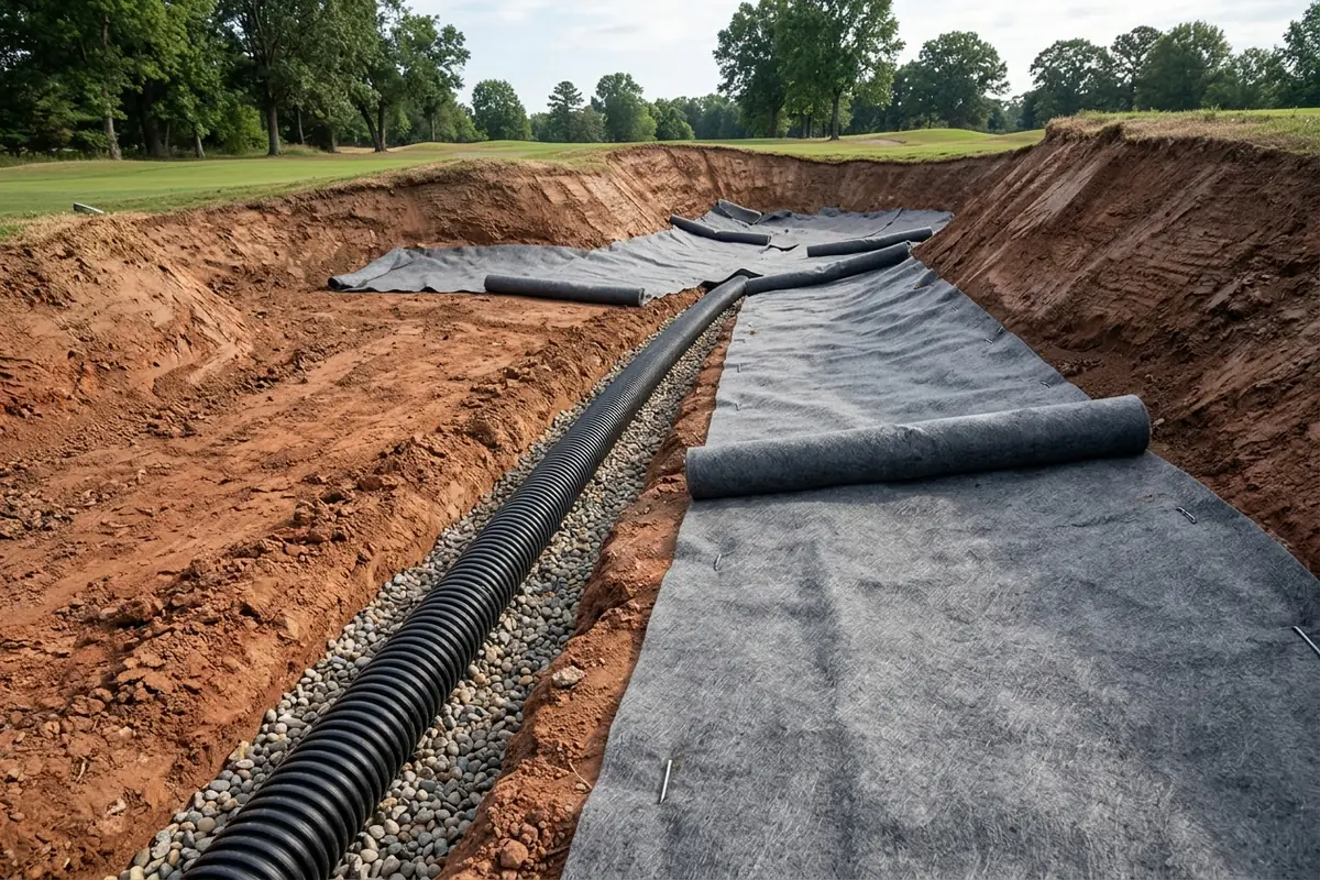
Subsurface Trench Geometry, Herringbone / Smile Pipe Layouts, and Outfall Verification
Across USGA construction surveys (Moore, 2008, p. 2; O’Brien, 1999, p. 14) and commercial liner installation standards (Sandtrapper by IVI-GOLF), internal bunker drainage follows four structural rules:
- Trench Dimensions &
4-Inch(100 mm) Perforated Pipe: Excavate drainage ditches8 inches(200 mm) wide by8 to 10 inches(200 to 250 mm) deep (Moore, 2008, p. 2)—or8 × 12 inches(200 × 300 mm) under the USGA Enhanced Bunker Drainage profile (O’Brien, 1999, p. 14)—into the compacted earth subgrade. Lay4-inch(100 mm/ DN100) smooth-wall or corrugated perforated plastic pipe (CPPorHDPE) along the trench floor and backfill completely with clean, washed1/4 to 3/8 inch(6 to 10 mm) pea gravel or crushed stone. - Lineal Pipe Density (
150 Linear Feetper1,500 sq ftBunker): Based on Golf Course Builders Association of America (GCBAA) and USGA survey benchmarks (Moore, 2008, p. 2), an average single bunker measures1,500 sq ft(~140 m²) (~100,000 sq fttotal bunker area across an 18-hole course with2 to 3+bunkers per hole) and requires approximately150 linear feet(~45 m) of4-inchperforated drainage pipe—a baseline engineering ratio of1.0 linear foot of drain pipe per 10 sq ft of bunker floor area. - Collector Geometry (Herringbone, Simple Y, and Toe Smile Drains): Orient all lateral drain trenches perpendicular to the slope of the bunker floor so sheet percolation is intercepted across the fall line (
Sandtrapper Drainage Planning). Small circular bunkers use a Simple Y layout; elongated or kidney-shaped bunkers use a central4-inchspine with angled Herringbone laterals; and bunkers with large, steep flashed faces add a curved Smile Drain along the toe of the steep slope to capture rapid face runoff before it scours the flat floor. - Mandatory Dyed-Water Outfall Test & Uphill Surface Runoff Diversion: Before attaching new internal bunker drain pipes to an existing underground outfall line during a renovation, flush dyed water through the original outfall pipe and visually confirm discharge at the downstream exit outlet (O’Brien, 1999, p. 14 (Step 2)). If tree roots, crushed tile, or silt have blocked the outfall, replace the outfall line first. Simultaneously, grade uphill surface-water diversion swales outside the bunker perimeter (O’Brien, 1999, p. 14 (Step 9)) so sheet runoff from surrounding fairways or green slopes cannot cascade over the bunker lip.
Comparing the 3 Bunker Liner Architectures
Installed between the compacted earth subgrade/drainage trenches and the bunker sand, a bunker liner prevents native subsoil silt, clay, and stones from migrating upward into the sand and reduces face washouts during storms (Moore, 2008, p. 2; O’Brien, 1999, p. 14). Course architects and superintendents choose among three structural liner systems:
- Roll-Out Non-Woven Geotextile & Synthetic Mat Liners (
Trevira,Sandtrapper): Heavy-duty synthetic filter fabrics or lofty fibrous mats rolled out like carpet over the shaped subgrade and anchored with metal sod staples. When only a portion of a bunker is lined or direct trench access is desired, installers carry the geotextile edges down into the8 × 10 in.drainage trench and secure them before placing the final gravel cover over the4 in.pipe (Sandtrapper), or cut the filter cloth over the drain slot and bridge the trench with three-dimensionalEnkamaterosion matting (O’Brien, 1999, p. 14 (Step 7)). Roll-out liners have the lowest material cost ($0.25 to $0.75/sq ftmaterial plus$1.00 to $2.00/sq ftinstallation in the 2008 USGA survey), but require strict sand-depth maintenance so mechanical rake teeth and wedge shots never snag or pull up fabric fibers (Moore, 2008, p. 2). - USGA Enhanced Bunker Drainage Method (
1.5–2.0 in.Pea-Gravel Blanket +7.5 ozTrevira+Enkamat): Developed by Billy Fuller (Cupp Design, Inc., formerly superintendent at Augusta National) and documented by Patrick O’Brien (USGA Green Section Record, 1999, p. 14), this 9-step architecture places a1.5 to 2.0 in.(38 to 50 mm) compacted blanket of washed1/4 to 3/8 in.pea gravel or crushed stone across the entire bunker floor over8 × 12 in.gravel trenches and4 in.smooth-wall perforated pipe. A7.5 oznon-wovenTrevirafilter cloth is stapled over the gravel blanket and bunker edges, paired with a precut plastic edge barrier stapled into the bunker sidewall (so edgers never cut the cloth) andEnkamatplaced over the cut cloth along the drain lines. Storm water drops through the sand into the continuous gravel blanket and reaches the drain tiles without dragging sand off the faces. - Sprayed or Poured Porous Aggregate & Polymer/Cementitious Sealant Liners (
CapillaryFlow, Polymer-Bound Stone): Instead of a fabric sheet, a~2.0 in.(50 mm) layer of polymer-stabilized washed aggregate or cementitious porous aggregate (> 20%interconnected void space) is sprayed, poured, or troweled directly over the shaped subgrade and gravel-filled drain trenches (Moore, 2008, p. 2;CapillaryFlow). Rigid porous-aggregate liners eliminate fabric snagging by mechanical rakes and stabilize steep bunker faces, though they require specialized contractor batching or representative installation and weekly sand-depth checks on steep faces so clubheads do not strike the hard liner surface.
| Bunker Liner Architecture | Structural Layer Composition | Trench & Edge Detailing | Relative Cost & Rebuild Lifespan (USGA 2008 Benchmark) | Primary Operational Advantage & Maintenance Rule |
|---|---|---|---|---|
1. Roll-Out Non-Woven Geotextile / Synthetic Mat (Trevira, Sandtrapper) |
Single or dual-ply non-woven synthetic filter fabric / lofty fiber mat stapled directly to compacted subgrade | Tuck liner into 8 × 10 in. gravel trench before top stone, or bridge trench slot with Enkamat |
Baseline roll-out material + high hand-pinning labor; stretches rebuild from 5–7 yr to 7–10 yr |
Fast contoured installation; requires hand raking on slopes and weekly depth probes to prevent rake/club snags |
2. USGA Enhanced Bunker Drainage Method (O'Brien 1999) |
1.5–2.0 in. washed pea gravel (1/4–3/8 in.) over floor + 7.5 oz Trevira filter cloth + Enkamat over trench |
8 × 12 in. trench with 4 in. smooth-wall perforated pipe + stapled precut plastic edge liner at lip |
Higher initial hand/wheelbarrow build cost (comparable to green build), offset by eliminating 60–100 hr storm shovel-backs |
Full-floor gravel plenum evacuates heavy cloudbursts laterally; plastic edge barrier protects cloth during trimming |
3. Sprayed / Spread Porous Aggregate or Polymer Sealant (CapillaryFlow) |
1.5–2.0 in. (38–50 mm) polymer-bound washed stone or cementitious porous aggregate matrix |
Poured or sprayed continuously over shaped subgrade and gravel-capped 4 in. perforated drain trenches |
Representative/specialty install (`$1.00–$1.50/sq ft` in 2008 USGA survey vs `$1.25–$2.75/sq ft` installed roll-out) | Zero loose fibers to snag rake teeth; rigid matrix locks steep faces; maintain >= 1–2 in. sand on faces to protect clubs |
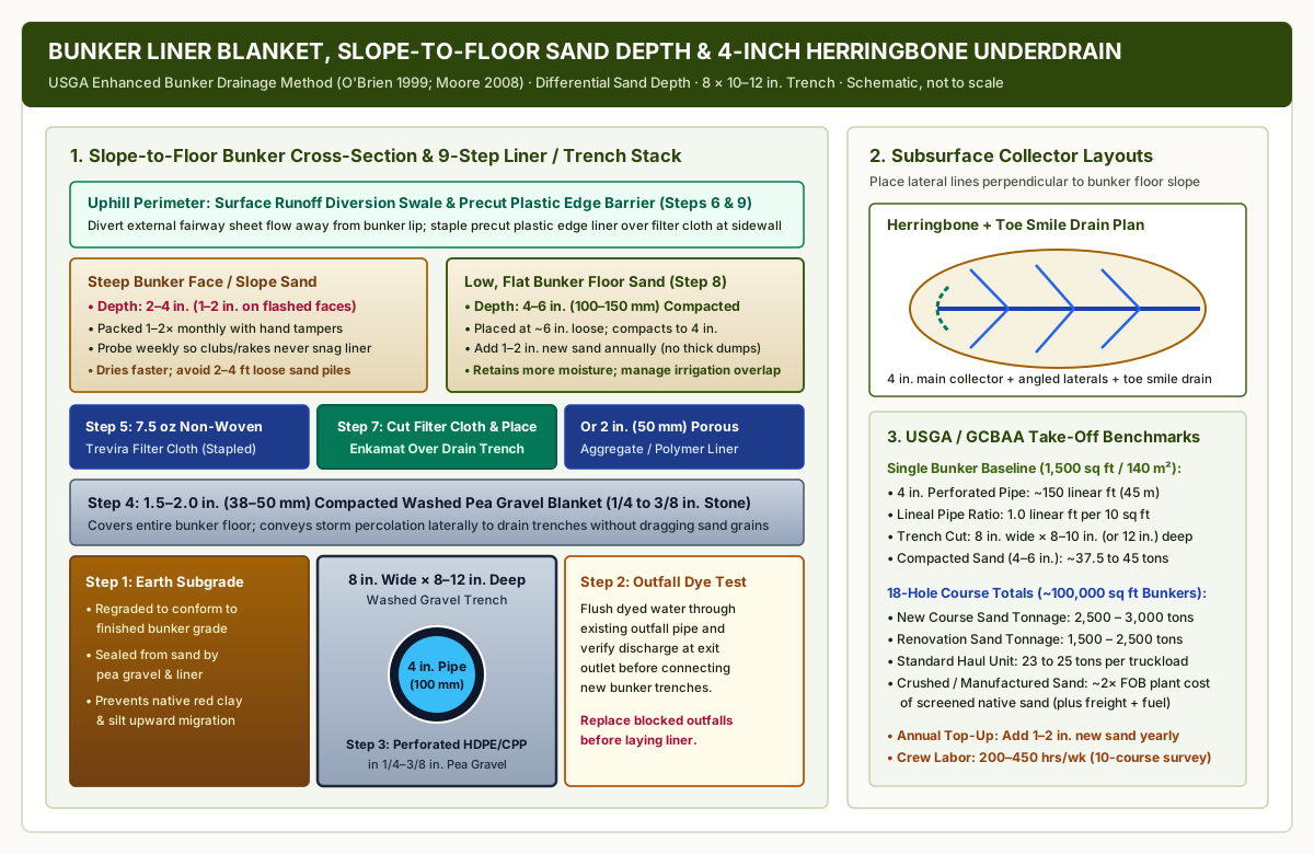
Differential Sand Depth Profile (4–6 in. Floor vs. 1–2 in. Steep Faces) and Moisture Balance
One of the most frequent construction errors in golf course renovation is specifying a uniform 5 to 6 inch sand depth across the entire bunker cavity. As Moore (1998, p. 12), Moore (2008, pp. 4–5), and Dr. Steve Kammerer (USGA Green Section Regional Update, Aug 16, 2019) detail, gravity and slope geometry require a differential depth and moisture management protocol:
- Low, Flat Bunker Floors (
4 to 6 in./100 to 150 mmCompacted): Install sand at approximately6 inches(150 mm) loose depth so it compacts to4 to 6 inches(100 to 150 mm) across the flat floor (O’Brien, 1999, p. 14). This thickness provides sufficient cushion for full explosion wedge shots and isolates the liner from deep mechanical or hand raking. - Moderate Slopes (
2 to 4 in.) and Steep Flashed Faces (1 to 2 in.Hand-Tamped): Sand is always maintained shallower on slopes and faces than on the floor (Moore, 1998, p. 12). On steep flashed sand faces, piling loose sand deeply (2 to 4 ftin older unlined builds) guarantees severe plugged lies and slumping; modern lined bunkers maintain1 to 2 inches(25 to 50 mm) on steep faces (and2 to 4 in.on transition slopes), probed weekly and re-established by hand shoveling so golfers never strike the liner, and packed once or twice per month with hand tampers to prevent ball plugging (Moore, 2008, pp. 4–5). - Managing Slope-to-Floor Moisture Disparities (
Kammerer, 2019): Even in bunkers equipped with durable liners and4-inchherringbone drains, gravity pulls moisture downward from high, sun-exposed sand faces into low-lying bunker floors, while frequent greenside turf irrigation throw patterns overlap into the bunker (Kammerer, 2019, pp. 1–2; Moore, 1998, p. 12). Superintendents reduce dry-face / wet-floor disparities by installing dedicated mist irrigation heads around bunker surrounds (keeping turf watered without flooding the sand), applying penetrant wetting agents to accelerate floor drainage, and adjusting hand raking vs. mechanical raking (hand raking produces a firmer, more play-consistent surface and protects shallow liners, whereas deep mechanical raking loosens and dries the upper sand layer). - Annual
1 to 2 InchSand Replenishment Rule: As wind, explosion shots, and post-storm skimming remove sand over time, add1 to 2 inches(25 to 50 mm) of matching Munsell-color sand annually across all course bunkers rather than waiting several years to dump a thick4+ inchlayer, which creates a soft, unplayable surface prone to buried lies (Moore, 1998, p. 11; Moore, 2008, p. 5).
Quantitative Material Take-Off & Logistics Formulas (1,500 sq ft Bunker & 100,000 sq ft Course)
When budgeting a bunker renovation or new course build, material quantities and haul logistics are governed by compacted sand depth, bunker square footage, and quarry distance (Moore, 2008, pp. 2–4; O’Brien, 1999, p. 14):
1. Subsurface 4-Inch Perforated Drain Pipe Length (L_pipe_ft):
   L_pipe_ft = A_bunker_sqft × 0.10 linear ft/sq ft

2. Compacted Bunker Sand Tonnage (T_sand_tons):
   T_sand_tons = A_bunker_sqft × (D_compacted_in / 12) × (gamma_sand_lb_ft3 / 2,000)
   (Using the USGA survey benchmark of 3,000 tons across 100,000 sq ft at 4–5 in. average depth = 0.030 tons/sq ft, or ~100 lb/sq ft per 12 in. compacted depth)

3. Washed Pea-Gravel Blanket Volume (V_gravel_yd3, for 1.5 to 2.0 in. Enhanced Drainage Blanket):
   V_gravel_yd3 = (A_bunker_sqft × (D_gravel_in / 12)) / 27

4. Over-the-Road Haul Truckloads (N_trucks at 23 to 25 tons per tri-axle / semi dump load):
   N_trucks = ceil(T_sand_tons / 23 to 25 tons/load)
Applying these USGA / GCBAA engineering relationships (Moore, 2008, pp. 2–4) to a single 1,500 sq ft (139.4 m²) greenside bunker and a full 18-hole 100,000 sq ft (9,290 m², ~66 bunkers) course program:
- Single
1,500 sq ftBunker Take-Off:4 in.(100 mm) Perforated HDPE Drain Pipe:1,500 sq ft × 0.10 = 150 linear feet(45.7 m) of pipe installed in8 in. wide × 8–10 in. (or 12 in.) deepgravel trenches.- Washed Pea-Gravel Blanket (
1.5 to 2.0 in.compacted1/4–3/8 in.stone):1,500 × (1.75 / 12) / 27 = 8.1 cubic yards(6.2 m³) of washed pea gravel beneath1,500 sq ft(plus10%–15%overlap/edge waste =~1,700 sq ft) of7.5 oznon-wovenTrevirageotextile or porous liner. - Bunker Sand Tonnage:
1,500 sq ft × 0.030 tons/sq ft = 45.0 tons(~2truckloads at23 tons/load).
- Full 18-Hole Course (
100,000 sq ftTotal Bunker Area) Benchmarks:- Total Sand Requirement:
2,500 to 3,000 tonsfor new golf course construction, or1,500 to 2,500 tonsfor a course renovation (Moore, 2008, p. 3). - Trucking & Crushing Multipliers: Hauling
3,000 tonsin23- to 25-tontruckloads requires120 to 131 truckloads. While screened native sand is mined and screened locally, manufactured (crushed) angular sand roughly doubles the FOB plant material cost (historically$30–$50/tonvs.$15–$25/tonFOB in the 2008 USGA survey), and long-haul trucking (100 to 300+ milesplus10% to 30%diesel fuel surcharges and state sales tax on material and freight) can equal or exceed the FOB cost of the sand itself (Moore, 2008, p. 3).
- Total Sand Requirement:
Accredited Laboratory Submittal & Renovation Verification Checklist
Before signing a sand supply contract or closing up subsurface bunker trenches, superintendents and project specifiers should verify every gate in the table below against the laboratory certificate and field mock-up:
| Verification Stage | Test Method / Standard Reference | Mandatory Acceptance Gate | Corrective Action if Out of Tolerance |
|---|---|---|---|
| 1. Quarry Sample Submittal | USGA Green Section (Moore 1998) |
Submit 1 gallon (3.8 L) dry sand per source to an accredited physical soil lab; allow 2–3 weeks |
Never order bulk tonnage from supplier sieve sheets alone without shape, penetrometer & crusting tests |
| 2. Sieve Gradation Analysis | ASTM F1632 / USDA Sieve Stack (No. 10 to No. 270) |
0.25–1.0 mm >= 65% (65%–75%+ greenside); Silt+Clay <= 3%; Fine+V.Fine < 25%; Gravel < 3%; Greenside V.Coarse < 7% |
Reject sands with > 3% gravel (mower damage) or > 25% fine sand (seals putting green rootzones) |
| 3. Grain Shape & Pocket Penetrometer | Microscopic shape grading + Brown & Thomas (1986) / PN5-S golf-ball penetrometer |
Angular / low-sphericity grains; lab penetrometer > 2.4 kg/cm² target (>= 1.8–2.2 kg/cm² min across 3–5 reps in >= 4 in. dry sand) |
Reject rounded, high-sphericity sands reading < 1.8 kg/cm² to prevent chronic "fried-egg" buried lies |
| 4. Crusting, Setup & Mineral Hardness | Overnight wet/dry spatula lift test + pH / acid effervescence & hardness test |
Spatula rating = None (N) for both 1/8–1/4 in. crusting and deep setup; hard quartz silica (pH <= 8.0) |
Avoid soft calcareous sands (pH > 8.0) that crush under rakes and precipitate carbonate scale in drain pipes |
5. Saturated Hydraulic Conductivity (Ksat) |
Klute (1986) / ASTM saturated soil column conductivity |
>= 20 in./hr (508 mm/h) minimum; clean straight bunker sand > 50 in./hr (1,270 mm/h) |
If existing aged bunker sand tests < 20 in./hr due to clay contamination, replace sand rather than only adding pipe |
| 6. On-Course Test Bunker Trial | USGA Partitioned Test Bunker (Moore 1998; Bigelow 2008) |
Divide practice/test bunker with 2 × 6 boards; test 2–3 lab-passed sands for 2–3 months; verify Munsell wet/dry color |
Calibrate lower field penetrometer readings and member playability preference before ordering 1,500–3,000 tons |
| 7. Outfall Dye Test & Herringbone Trenches | USGA Enhanced Bunker Drainage (O'Brien 1999; Moore 2008) |
Flush dyed water through outfall to exit; cut 8 × 10–12 in. trenches with 4 in. perforated pipe (~150 ft / 1,500 sq ft) + uphill runoff swales |
Replace blocked outfalls before tie-in; orient lateral trenches perpendicular to bunker floor slope |
| 8. Liner Cover & Differential Sand Depth | Weekly depth probe + hand tamper schedule (Moore 2008) |
4–6 in. (100–150 mm) compacted on floor; 2–4 in. (1–2 in. steep face) on slopes; pack faces 1–2×/mo; add 1–2 in./yr |
Probe liner cover weekly so wedges and power rakes never snag liner; skim storm silt layers immediately after pumping |